The Model 845 Signal Generator (and the multi-channel Model 855B) with option FS steps through a sweep with a minimum step time of 40 µs and a 30 µs transient time (Model 845 datasheet, Sweeping & Switching). Combined with the trigger system, the sweep engine generates frequency and power ramps that external equipment can follow point by point. In contrast to an analog sweep, a digital sweep can be synchronized at any point during the sweep, and every point is a synthesized frequency with the generator's 0.001 Hz resolution.
1Introduction
The Model 845 and Model 855B Signal Generators can be programmed to execute sweeps either from the BNC graphical user interface (GUI) or directly with SCPI commands.
In this application note, we describe the configuration for a frequency sweep with the following parameters:
- Linear sweep from 1 to 12 GHz in total 10 steps
- Execute entire sweep once on every external trigger rising edge
- Frequencies shall be switched every 50 µs
- An output trigger shall provide a "signal valid" indication by changing to HIGH whenever the transient is completed and the signal becomes valid
2Timing
TRIG OUT goes high as soon as the first frequency is valid and remains high until t = 50 µs, when switching to the next frequency is initiated. Within the transient time τinv the switching transient completes and TRIG OUT goes high again. The new frequency and power pair remains stable until t = 100 µs, when TRIG OUT goes low for a second time and the next frequency and power pair is programmed (Figure 1).
The transient time τinvN and the valid time τvalN can vary from point to point, but the step time τstep (= τinvN + τvalN) between frequencies is always 50 µs. For the first frequency of the sweep, τinv1 is zero and τval1 is 50 µs.
TRIG OUT synchronizes the sweep to external equipment with a timing accuracy of 5 ns per point (option FS).
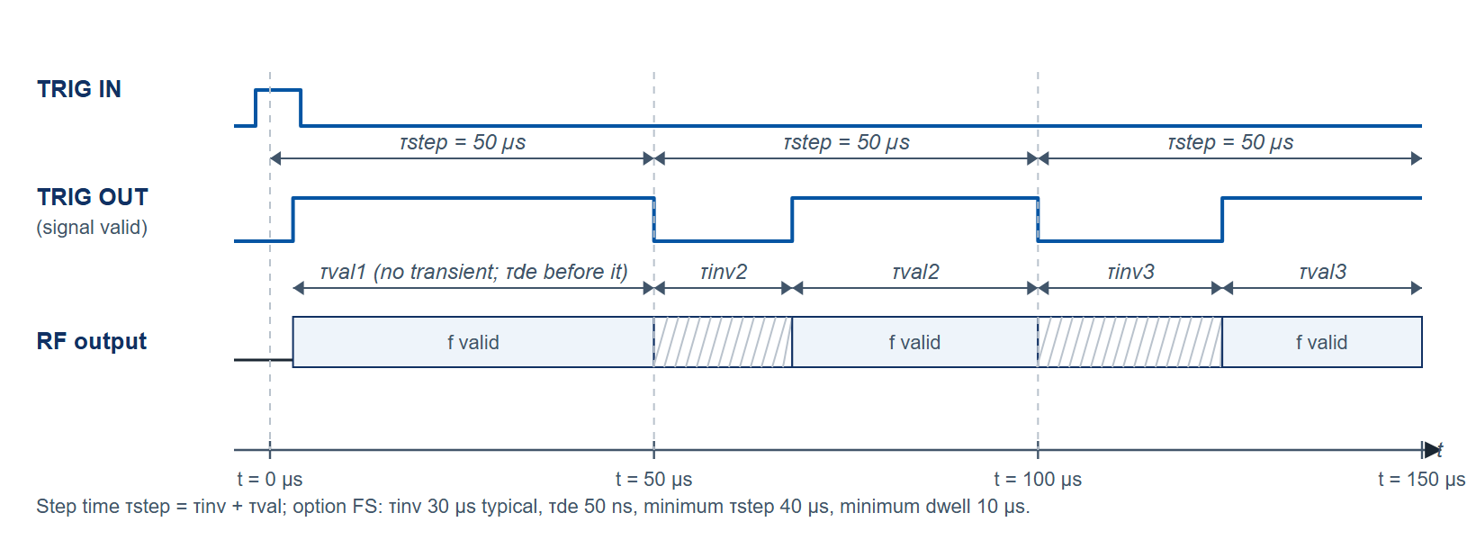
3Sweep Configuration
We configure this sweep in three steps:
1. Configure Trigger
Trigger input:
| Command | Value |
|---|---|
| TRIG:SEQ:TYPE | POIN |
| TRIG:SEQ:SOUR | EXT |
| TRIG:SEQ:DEL | 0 |
| TRIG:SEQ:SLOP | POS |
| TRIG:SEQ:ECO | 1 |
Trigger output:
| Command | Value |
|---|---|
| TRIG:OUTP:MODE | VAL |
2. Configure Sweep
| Command | Value |
|---|---|
| SOUR:SWE:COUN | 1 |
| SOUR:SWE:DWEL | 50e-6 |
| SOUR:SWE:DEL | 0 |
| SOUR:SWE:SPAC | LIN |
| SOUR:SWE:POIN | 10 |
| SOUR:SWE:STAR | 1e9 |
| SOUR:SWE:STOP | 12e9 |
| SOUR:FREQ:MODE | SWE |
3. Arm Trigger
| Command | Value |
|---|---|
| INIT:CONT | ON |
4Key Specifications
- Output power -20 to +15 dBm standard; -90 to +13 dBm with option PE; up to +21 dBm (0.01 to 12 GHz) with option HP
- Frequency and amplitude setting time 30 µs with option FS (200 µs standard); minimum step time 40 µs with option FS, minimum dwell time 10 µs
- SSB phase noise -118 dBc/Hz typical at 4 GHz, 20 kHz offset
- Continuous, single, gated and gated-direction triggering; linear, logarithmic, random and list sweeps
- Models 845-12, 845-20 and 845-26 (100 kHz to 12, 20 or 26 GHz), desktop or 19 inch 1U rack mount (option 1URM)
5Graphical User Interface (GUI) Setup
The same sweep can be set up in the GUI. First, we configure the trigger system to wait for a rising edge and run the entire sweep on each trigger.
We switch to the TRIGGER tab of the GUI as shown in Figure 2. We set trigger mode to "Repeat", Trigger source to "External Trigger", Trigger Edge to "Rising", and Trigger Parameter to "Execute complete List". In the trigger output setting we set "Valid".

Next, we switch to the SWEEP tab of the GUI as shown in Figure 3.
We set the start frequency to 1 GHz, and stop frequency to 12 GHz. The number of repetitions of the sweep we set to 1, number of points to 10, "Dwell time" to 0.05 ms, disable the "Auto" and set the "Off time" to 0 ms.
We can choose for the ALC (automatic level control) to operate in "on" or "hold" mode. We can start the sweep with the "on/off" button on the left.

6Applications
- ATE
- R&D low noise signal source
- Production testing (fast switching, high dynamic range)
- Service and maintenance (battery operation with option EB6)
- Signal simulation (radar, UWB)
- Aerospace and defense (pulse modulator, chirps)
7Measurement Results
Figure 4 shows the time domain measurements of the sweep. TRIG IN is applied approximately every 990 microseconds from an external source (red trace). Upon the rising edge, the "signal valid" (green trace) goes high almost instantly, indicating that the first frequency RF (blue trace) is stable. After the ten consecutive frequencies, "signal valid" goes low a last time and remains low until a new sweep starts upon a new trigger rising edge.

8Conclusion
Option FS on the Model 845 steps a digital sweep every 40 µs or longer, and the TRIG IN and TRIG OUT signals keep that sweep synchronized to external equipment to within 5 ns per point.