July 22nd, 2022 - Unipolar vs Bipolar Pulses
What’s the Difference Between Unipolar and Bipolar Pulsers?
High voltage pulsers are available in two general categories, unipolar and bipolar.
-
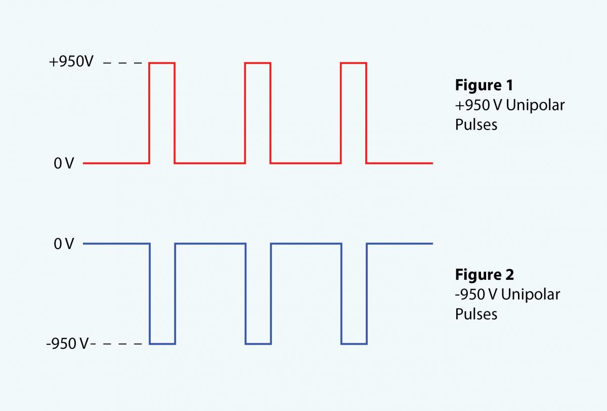
A unipolar pulser generates single-polarity voltage pulses. The output voltage is zero between the pulses.
-
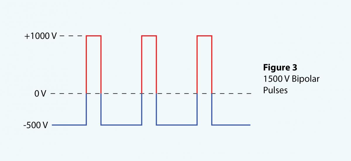
A bipolar pulser generates dual-polarity voltage pulses. The output voltage alternately swings between positive and negative.
In either case, the amplitude of the pulses is set by a high voltage DC supply. It may be internal or external to the pulser depending on the model.
Unipolar Pulsers
For a unipolar pulser, pulse polarity is set by design and indicated in the model number.

For example, the PVM-1001-P generates positive pulses up to +950 V (Fig. 1). The output is 0 V when the trigger input is low and +950 V when high.
The PVM-1001-N generates negative pulses up to -950 V (Fig. 2). The output is 0 V when the trigger input is low and -950 V when high.
Unipolar pulsers cannot be used in applications requiring pulses of both polarities.
Bipolar Pulsers
Bipolar pulsers can generate both single-polarity and dual-polarity pulses. In this case the positive supply is set to +1000 V and the negative supply is set to -500 V, resulting in 1500 V bipolar pulses.

Fig. 3 shows an example of a bipolar pulse generated by a PVX-4150.
Sometimes the terms bias voltage or offset voltage are used to describe the pulser’s “resting” voltage.
As we’ll see, a bipolar pulser can also be configured as a unipolar pulser if desired.
How a Unipolar Pulser Works

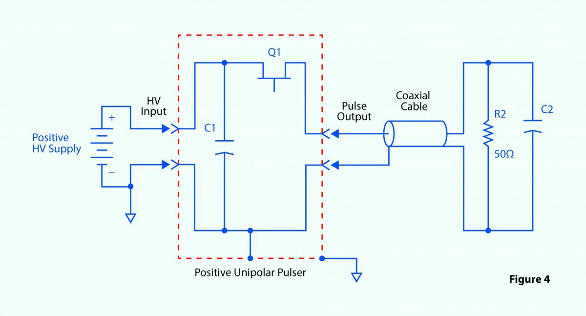
Power MOSFET Q1 is a fast switch that allows the stored energy to flow to the 50 Ω load. C2 represents the capacitance of the load and its connecting coaxial cable.
Figure 4 depicts a positive unipolar pulser. C1 is an energy storage capacitor.
The pulse rise time (when Q1 turns ON) is quite fast and is specified in the pulser datasheet. But the fall time (when Q1 turns OFF) is not guaranteed because no active component discharges the load capacitance. Instead, it’s discharged by the impedance of the load – although the fall time is still quite fast with a load resistance as low as 50 Ω.
How a Bipolar Pulser Works

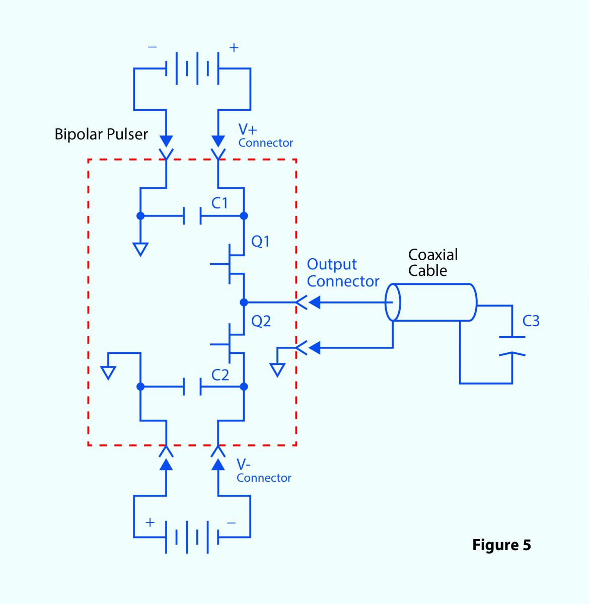
Power MOSFETs Q1 and Q2 are connected in a “half bridge” configuration (in higher-voltage pulsers, Q1 and Q2 are strings of series-connected power MOSFETs). C3 is the load capacitor.
The upper and lower driving circuits are opposite in polarity but otherwise identical; one charges the load capacitance and the other discharges it. This design delivers pulses with rise and fall times that are fast and symmetrical, important features for many applications.
Figure 5 illustrates a bipolar pulser such as the PVX-41xx series.C1 and C2 are energy storage capacitors.
Positive-Only Pulses with a Bipolar Pulser
Let’s say we need +1000 V unipolar pulses from a PVX-4150 bipolar pulser.
Using the coaxial cable assembly from the accessory kit, we connect a +1000 V power supply to the pulser’s V+ input (positive to the center conductor, negative to the shield).
We do not need a negative power supply, so we connect the pulser’s V− input to ground.
We turn the pulser ON and then enable it via the front panel switch.
When the pulser’s gate input is low, Q1 is OFF and Q2 is ON. Because the pulser’s V− input is grounded, the output is at 0 V.
Driving the gate input high turns Q1 ON and Q2 OFF. This connects the V+ input to the output. Electrons flow from C3’s upper plate to the positive power supply, making the upper plate positive. Electrons flow from ground to the lower plate because they are attracted by the positively-charged upper plate. In a few dozen nanoseconds the capacitor is charged with its upper plate at +1000 V with respect to ground.
Driving the gate input low again turns Q1 OFF and Q2 ON. This connects the V− input to the output. Electrons flow from ground to C3’s upper plate, and from its lower plate to ground, quickly discharging it.
Negative-Only Pulses with a Bipolar Pulser
Assume we now need −500 V unipolar pulses from the same pulser.
We connect a −500 V power supply to the pulser’s V− input (negative to the center conductor, positive to shield).
We do not need a positive supply, so we connect the pulser’s V+ input to ground.
We turn the pulser ON and then enable it.
When the gate input is low, Q1 is OFF and Q2 is ON. This connects the V− input to the output. Electrons flow from the −500 V supply to C3’s upper plate. Electrons on the lower plate are repelled and flow to ground. C3 is quickly charged with its upper plate at −500 V with respect to ground.
Driving the gate high turns Q1 ON and Q2 OFF. This connects the (grounded) V+ input to the output. Electrons piled up on C3’s upper capacitor plate flow to ground. The lower plate is short of electrons and draws them from the V− input, and C3 is quickly discharged.
Be Sure to Ground the Non-Powered Input
The above explanation shows how important it is to connect the non-powered input (V+ or V−) to ground when generating unipolar pulses. Leaving the non-powered input unconnected means the load capacitor lacks a current path for either the charge or discharge portion of the pulse. This results in an extremely long edge time.
Bipolar Pulses with a Bipolar Pulser
Now assume we need bipolar pulses consisting of +1000 V pulses with a −500 V bias.
We connect a +1000 V power supply with the positive terminal to the pulser’s V+ input and the negative terminal to the pulser’s ground.
We also connect a −500 V power supply with the negative terminal to the pulser’s V− input and the positive terminal to the pulser’s ground.
The pulser operates as described previously; the output will be +1000 V when the gate input is high and −500 V when the gate is low. To invert the operation (−500 V pulses with +1000 V bias), invert the output of the pulse device feeding the gate input.
Don’t Exceed the Specs
Note that voltage pulsers are specified with a maximum voltage from V+ to ground, V− to ground, and the absolute difference between V+ and V−. Exceeding this specification will damage the pulser.
For example, the PVX-4110 is a 10 kV pulser. It can generate +10 kV unipolar pulses, −10 kV unipolar pulses, +9 kV to −1 kV bipolar pulses, and so on. Connecting V+ to +6 kV and V− to −5 kV exceeds the specification even though neither input exceeds 10 kV to ground.
Don’t Float This Boat
A note of caution: It is never recommended to “float” a pulser, whether the purpose is to add a very high bias voltage or to stack pulsers to generate higher voltage pulses. It is difficult to synchronize such a setup; even worse, everything connected to the pulser must float as well. This includes all power supplies, logic pulse sources, and test equipment. The "ground" for the floated equipment may be dangerously above real ground resulting in shock to personnel and/or damage to equipment.
