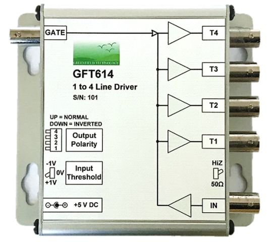
GFT614 | 1 to 4 Line 50 Ω Driver Module
The GFT614 module is specially designed for distribution of high frequency clock and high-speed logic signal to multiple devices via long cable. All outputs with 50 Ω load can drive 100 feet of cable at clock rate greater than 200 MHz with 2.5 V amplitude.
The channel input threshold can be set to +1 or 0 or -1 V and the input load can be selected from 50 Ω or 1 KΩ pull up by a front panel switch. So that channel input can be driven directly by TTL / CMOS logic levels or open collector or negative pulse (0 to -3 V) or AC coupled signal (± 0.5 V).
All outputs with 50 Ω load can drive 100 feet of cable at clock rate greater than 150 MHz with 2.5 V amplitude. Each output polarity can be set normal or inverted and outputs are compatible with DC or AC TTL input.
A gate input allows to disable the module by external signal.
The GFT614 is a compact module supplied with a +5 V AC/DC adapter.
Overview
Features
- Up to 150 MHz clock rate
- Drive 100 feet of cable at 150 MHz
- Four synchronized 50 Ω TTL outputs
- 1 ns typical output rise & fall time
- Selectable polarity
- 2 ps input to output RMS jitter
- One input with:
- Selectable threshold (+1 V / 0 V / -1 V)
- Selectable load 50 Ω or 1 kΩ pull up
- Active low Gate input
- Operate from DC +5 V
- All input & output are BNC connectors
- Compact module: 115 X 103 x 37 mm
- Option: 4 individual 50 Ω TTL line drivers
Applications
- Clock distribution
- 1 to 4 splitters
- Pulse inverted
- Level translator
- Converting sinewave to square wave
- Long Line Drivers
- Tools for Lab
- Components Test equipment
Specifications
Input
Range
+5 V to -5 V
Threshold Level
+1 V or 0 V or -1 V (selectable at rear panel)
Internal Load
50 Ω or 1 kΩ pulled to +5 V (selectable at front panel)
Minimum Pulse Width
5 ns
Output
Number
4
Output Resistance
50 Ω
Low Level
0.25 V
High Level
2.5 V @ Load=50 Ω, 4 V @ Load > 10 kΩ
Polarity from Input
Normal or inverted
Rise/Fall Times
1 ns / 1 ns @ 100 MHz square wave
Jitter RMS
2 ps (input to output)
Max Clock Frequency
150 MHz @ cable length = 3 feet
150 MHz @ cable length = 100 feet
Skew
500 ps (TBC)
Gate
Low Level
< 0.5 V
High Level
2.4 V
Rate
50 MHz
General Specifications
Control
Switches to select:
- Input load
- Input threshold level
- Output polarity: normal or inverted
Power on indicator
Inputs & Outputs
All are BNC connectors
Size
W = 115, L = 103, H = 30 mm
Mounting Flange
included
Power V/A
+5 V / 200 mA max.
External AC (90 -240 V) to DC (+ 5 V) adapter furnished
Power Connector
Jack 2.10 mm
Option
GFT644 module
4 individual 50 Ω TTL line drivers
Technical Resources
Downloadable Resources
Price Lists
Price lists are available to our registered users. To view pricing for this and other products, please log in or create a free account.