GFT1004 | 4-Channel 1 pS Digital Delay Generator Up to 10 Channels Optional [Obsolete]
The GFT1004 is a multi-channel digital delay generator that functions either as a standalone or as a component in a timing system. As a standalone instrument, it will produce multiple channels of delays which can be triggered by an external trigger or by selectable internal triggers. As a component of a timing system, the GFT1004 (with option 1) is operated in conjunction with a GFT3001 master transmitter. The 3001 is the master transmitter that controls a number of 1004’s to provide timing, triggering, gate, delay, and inhibit signals. A serial data stream over optical fiber provides clock synchronization, single shot triggering, repetitive triggering, and inhibit information to the various 1004’s at distances greater than 1 km from the GFT3001 master transmitter.
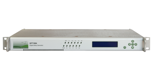
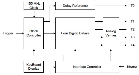
The GFT1004 rackmount Digital Delay Generator provides four/eight/ten independent delay channels from a single trigger input or internal clock. The delay resolution on all channels is a remarkable < 1 ps and channel to channel jitter is less than 15 ps rms. BNC outputs on the rear panel deliver up to 10 V levels into 50 Ω. One Trigger Input channel (T0, zero delay) is used to reference the four output channels in a variety of different operation modes.
The input connector, also on the rear panel, allows you to use an external trigger and still keep trigger jitter to a minimum. Electrical or Optical inputs are accommodated using a variety of operating modes. Delay parameters and operation modes may be programmed using the front panel interface or using remote programming over Ethernet.

In regards to limited quantity, please contact BNC about current stock and our recommended replacement model.
Overview
Features
- Four / Eight / Ten Independent Delay Channels
- < 1 ps delay resolution
- < 15 ps rms jitter
- Maximum Delay of 10 Seconds
- Rack 19″, 1U
- Scaleable to 100’s of Channels
- Remote or Local Programming Options
Service Advantage
- Components Test
- ATE Application
- Laser Timing Application
- Precision Pulse Application
- Synchronous Multi-channel
- Triggering
Specifications
Delay
Channels
4 independant (8/10 opt.)
Range
0 to 10 seconds
Resolution
1 ps
RMS Jitter
< 10 ps + delay x 10-7
Accuracy
< 150 ps + delay x 10-7
Trigger Delay
< 100 ns (insertion delay)
Time Base
0.5 ppm
External Trigger Input
Repetition Rate
Up to 1 MHz
Trigger Level
+1 V/ 50 Ω
Slope
Positive
Connector
BNC
Internal Trigger
Two Generators
Frequency = 1 Hz to 1 MHz in step of 1 Hz
Output Pulse T1 to T4
Amplitude
2.5 V to 10 V in step of 10 mV
Load
50 Ω
Rise/Fall Time
1 ns / 3 ns
Width
100 ns to 10 ms in step of 6.43 ns
Connector
BNC
External Time Reference
Frequency
10 MHz (other frequency are available up to 80 MHz)
Inhibition Input
Inhibition Input
Trigger level = 1 V, repetition rate < 1 kHz
General
Software
Free drivers for seven
User Interface
Front panel, Ethernet 10/100 Mb/s, Internet (Web page)
Power Consumption
90 To 240 V / 50 – 60 Hz/ 0.25 A
Weight
< 5 kg
Size
19″ W X 363 mm D X 1U H
Shipping Dimensions
24 x 19 x 13″
Shipping Weight
33 lbs
Options
Option 1
Extension to 8 channels
Option 2
Optical input for timing system mode
Option 3
Clock output
Option 4
32 V channel output (W=1 µs, rise/ fall time = 2/10 ns under 50 Ω)
Option 5
Extension to 10 channels
Option 6
5 V to 20 V channel output (W=0.1 to 10 µs, rise/ fall time <5 ns under 50 Ω)
Option 7
TTL level (2.5 to 6 V) channel output (positive or negative pulse)
Option 8
Optical channel output
Technical Resources
Downloadable Resources
Price Lists
Price lists are available to our registered users. To view pricing for this and other products, please log in or create a free account.
