
March 1, 2023 - Model 685 Series: AWGs for Optics, Photonics, and Lasers
Introduction
Nowadays the applications based on optics, photonics and lasers are becoming extremely popular and the latest generations of scientists are opening new territories for their real-world usage like lidar for automotive, medical solutions, aerospace & defense, quantum and laser sensors.
The testing challenges, time-to-market tasks, and the increasingly demanding applications identified the modern state of the art Arbitrary Waveform and Function Generators as the right choice to face these challenges. AWGs provide a flexibility that has never been seen before, giving engineers a powerful instrument to produce all types of pulses, signals and modulations. The Model 685 Series targets key issues including generating pulses for optics, photonics, and laser applications. This results in a device that accelerates testing, reliability, characterization of optics & photonics systems, as well as reduces time period to generate pulses and control signals for lasers and electro-optic modulators.
The different applications require different types of signals; AWG application examples are listed below:
- Generation of high amplitude and high speed pulses to drive directly the electro-optic modulators.
- Generation of different kinds of signals and pulses to make stimuli for quantum optics applications.
- Generation of pulses to drive the pulsed laser diodes.
Electro-optic Modulators
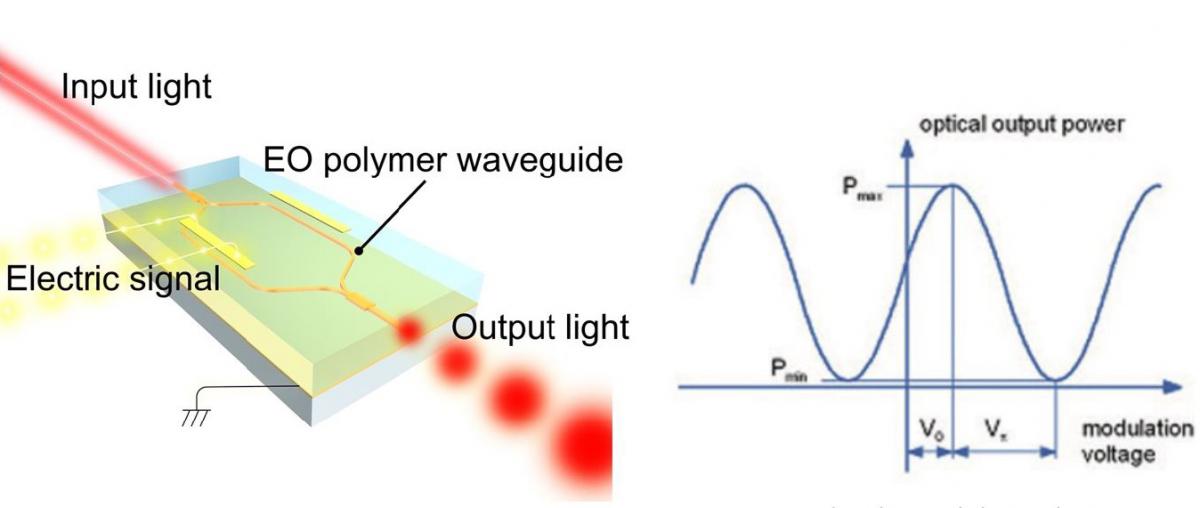
Integrated-optical waveguides are able to guide light along a determined path analog to optical fiber. The waveguide consists of a channel with higher refractive index compared to the surrounding material.
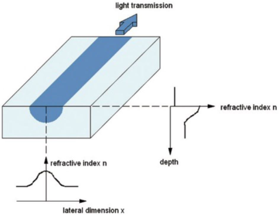
The light is guided by means of total internal reflection at the channel walls. Depending on the wavelength, substrate refractive index, refractive index difference, width and depth of the channel, one or more transverse oscillation modes can be excited. The single mode operation is of great interest since it is essential for the function of many integrated-optical elements. Integrated-optical elements are usually provided with optical fibers particularly in optical communication technology.
The linear electro-optic effect, also known as Pockels-Effect, is a second order non-linear effect, consisting in the change of the refractive index of an optical material if an external electric field is applied. The amount of change in refractive index is proportional to the electric field strength, its direction and the polarization of the light. The preferred material for the fabrication of integrated-optical modulators is Lithium niobate (LiNbO3). If an electric field is applied to a waveguide using electrodes of the length L, the refractive index changes in the area between the electrodes, giving a phase shift of the guided light. The phase shift is linear to the applied voltage.
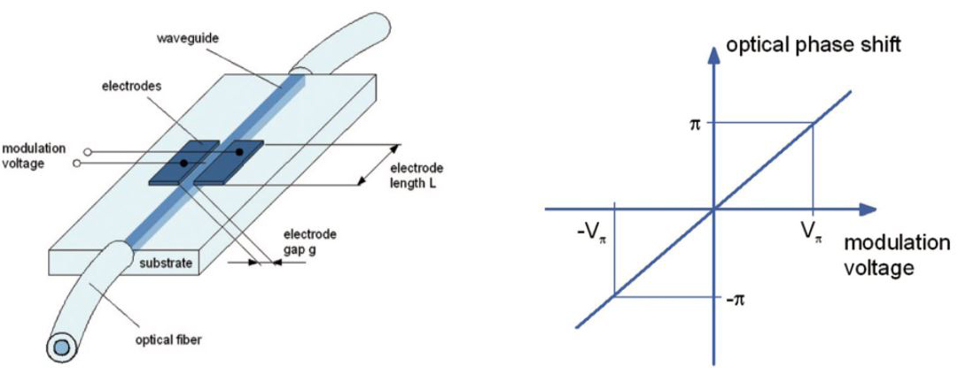
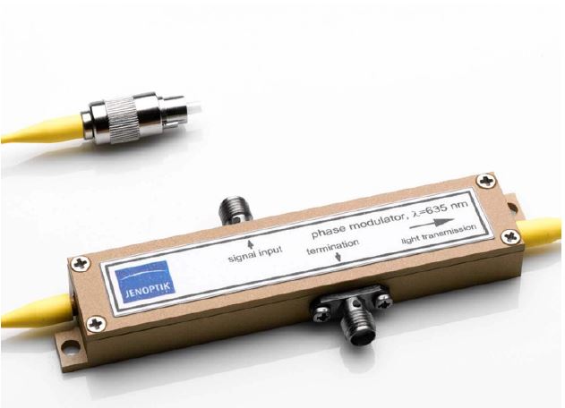
This typically amounts to a few volts. For longer wavelengths it is higher than for shorter ones at a given electrode geometry. For example it can be expected to be 3 V in the red (635 nm) and 10 V in the telecommunication wavelength range (about 1550 nm). Due to the very fast electro-optic response, the low control voltages and the use of sophisticated electrode geometry, it is possible to achieve modulation at frequencies in the gigahertz range. A phase modulator is inserted into an integrated Mach-Zehnder interferometer to form an amplitude modulator.
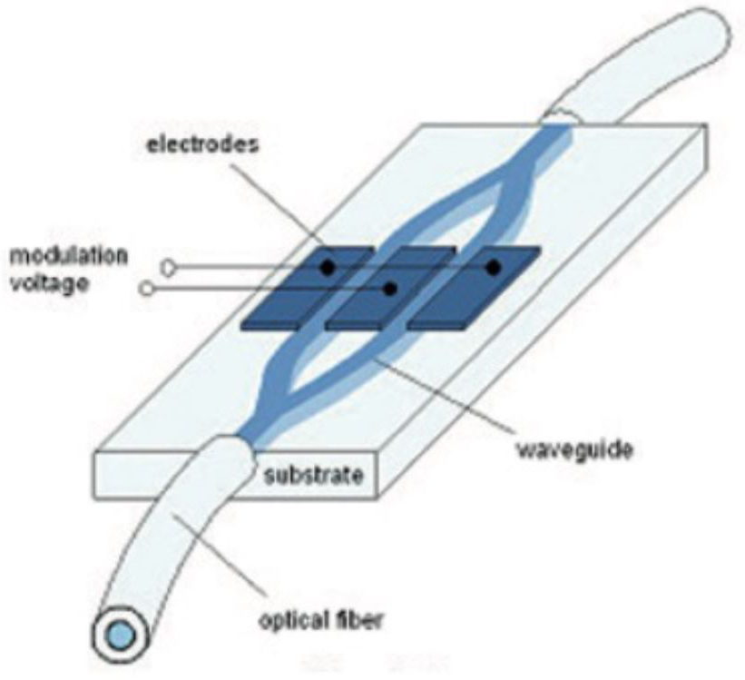
Applying a voltage leads to a relative phase difference between the branches, which causes a change of the output power at the device output by means of interference. So the device transmission can be controlled between a minimum and a maximum value (P min to Pmax ). A relative phase difference of π is needed for switching from on to off state or vice versa. The needed voltage is called the half wave voltage Vπ of the amplitude modulator. Due to the push-pull operation the half wave voltage of an amplitude modulator is the half of that of a phase modulator with equal electrode length. For example it can be expected to be 1.5 V in the red at 635 nm and 5 V in the telecommunication wavelength range about 1550 nm.
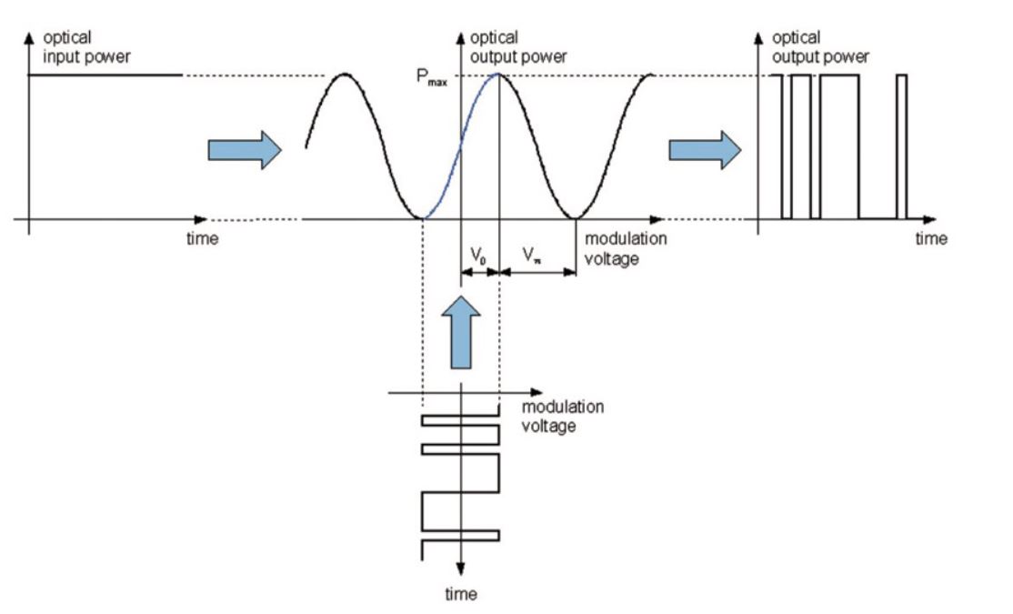
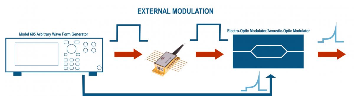
Applying a RF signal as modulation voltage to the electrodes, this electrical input is translated into an amplitude information. This amplitude output depends on the voltage magnitude and shape, thus related to the position of the modulator's operation point. The figure depicts the transmission of a binary pulsed electrical input into a binary optical output signal. If the voltage levels would not be correct, that is that the voltage is too high or the offset is not correct the modulator will react with non correct optical output levels in binary operation or with higher harmonics in analog operation.
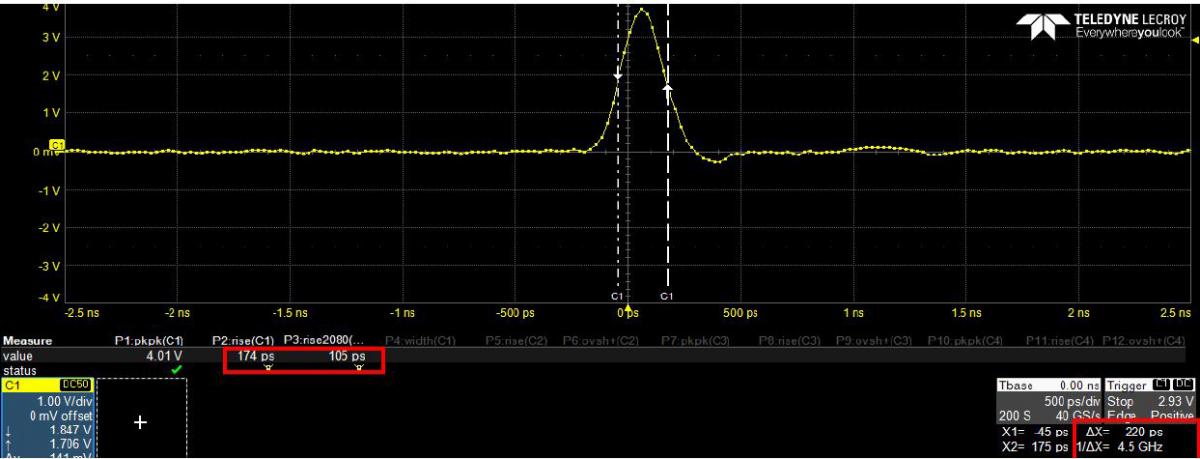
The Model 685 Arbitrary Waveform Generators allows you to create the modulation voltage by generating very narrow pulses (the minimum pulse width is 230 ps) with up to 5 Vpp amplitude. The high amplitude output signal, combined with 110 ps of rise/fall time (5 Vpp @ 2 GHz Bandwidth), gives you the possibility to directly drive different types of electro-optical modulators without adding an external amplifier.
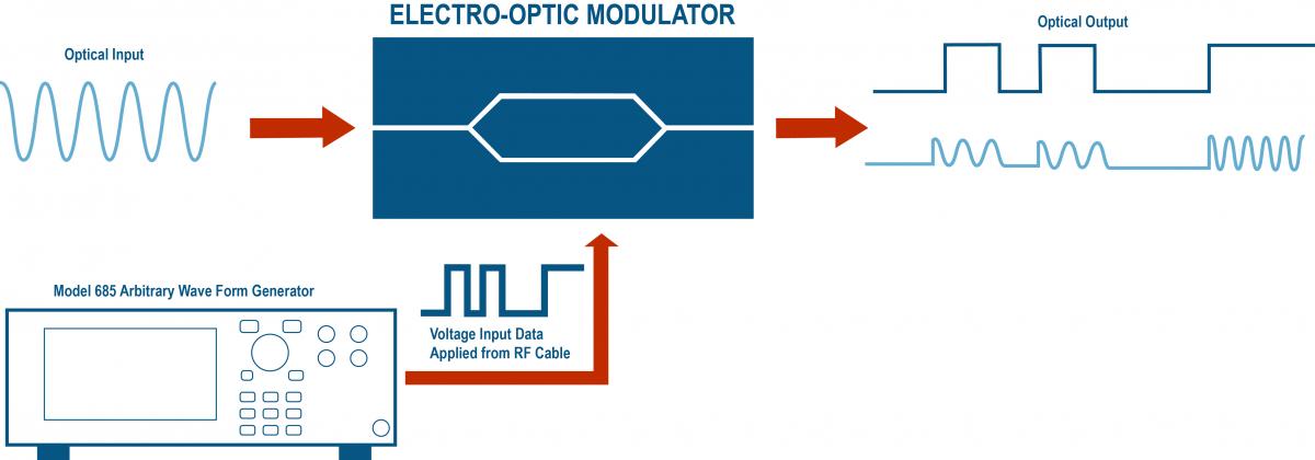
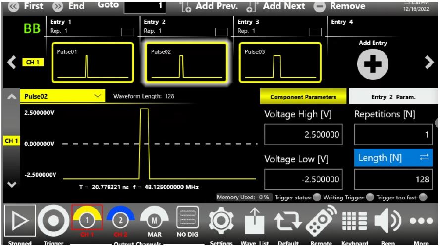
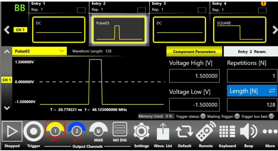
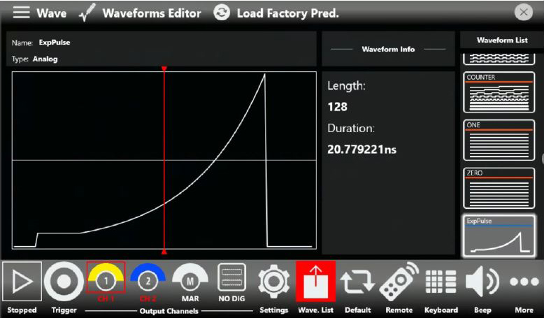
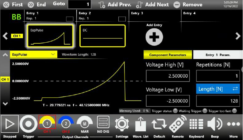
Thanks to the True-ARB User Interface, it is possible to easily generate different pulse’s shapes giving a more in depth control of optical output signal.
Quantum Optics
Color centers in diamond are defects in the crystal lattice, where carbon atoms are replaced by different kinds of atoms, and adjacent lattice sites are empty. Due to their bright single photon emission and optically accessible spins, color centers can be promising solid state quantum emitters for future quantum information processing and quantum networks. Two of the most mature systems that enable the entanglement of spin qubits and coherent photons are quantum dots and the nitrogen vacancy (NV) center in diamond. However, between these two systems, NVs exhibit excellent coherence times exceeding 1s, but lack efficient emission into the zero-phonon line (ZPL) required to yield indistinguishable photons, whereas quantum dots have shown great promise in emission properties but are limited to tens ns coherence times.
This highlights the typical challenges working with solid state quantum emitters:
- single photon generation
- the emitter spin coherence times
Recent investigations into group IV vacancy centers in diamond in partivular SiV ones, show promising results in meeting these fields.
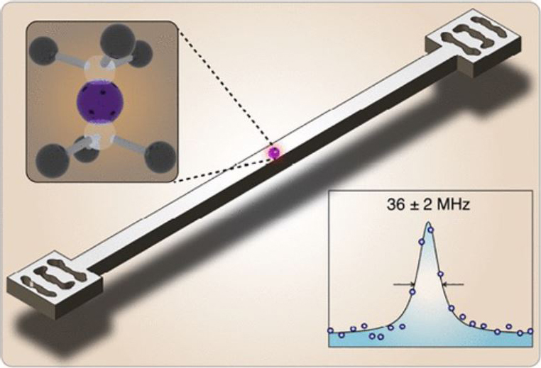
In combination with their good spin properties, tin-based vacancy centers are well suited for integration into nanophotonic platforms because of their strong and stable zero-photon line emission in nanostructures.
Group IV vacancy centers in diamond show excellent optical properties due to their crystallographic symmetry which favors emission into ZPL. SiV centers show 10 ms coherence times at 100 mK, while SnV has been predicted to give similar times at 2 K - a readily accessible temperature with standard helium cryostats.
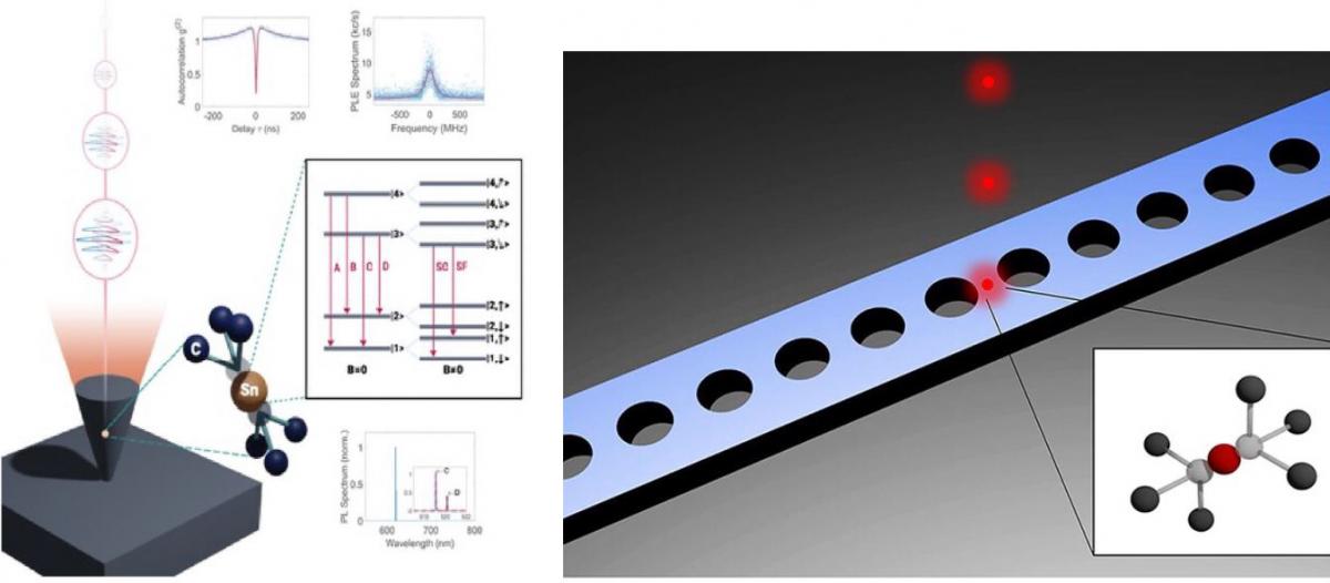
The Model 685 has been used to control the experimental pulses’ sequences used to manipulate single tin vacancy centers in diamond.
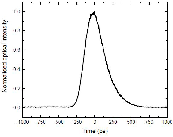
The Model 685 allows generating narrow electrical square pulses with high amplitude (>1.5V) to control an electro-optical amplitude modulator in order to generate short laser pulses.Using this mechanism, it is possible to generate optical pulses with a close to Gaussian shape exhibiting a full-width-half-maximum as narrow as 280ps. Furthermore, the Model 685 has been used to drive an electro-optical phase modulator for generation of frequency sidebands up to about 2GHz, enabling driving of two optical transitions with phase-stable laser fields.
The digital output channels of the Model 685, allow to control acousto-optical amplitude modulators or they are used to generate trigger pulses for timing of experimental sequences. In the future, it will be necessary the real time control of the measurement protocols depending on the outcome of a certain readout within the sequence.
Pulsed Laser Diode Driver
The ability of pulsed laser diodes to provide short pulses of intense power has made them an ideal choice for military applications such as target designating and range-finding. Indeed, much of the historical motivation for developing these diodes has military roots. However, today’s technology improvements and cost reductions are opening new applications in metrology and medicine.
Continuous vs. pulsed operation
Standard laser diodes are designed to emit CW radiation with power from a few milliwatts to a few watts. A pulsed laser operates at a lower duty cycle, so heat removal is less of an issue. Another design difference between pulsed and CW lasers is that the reflectivity of the pulsed laser’s output facet is generally much lower. Thresholds are kept low on typical CW lasers by limiting the emitting width to 5 to 35 μm. Although laser threshold current is directly proportional to this width, the high gain generated in pulsed lasers allows the width to be increased up to 400 μm with a corresponding increase in peak power. Unfortunately, without precautions, this combination of width and a short resonator at high gain can result in rotating modes in which the circulating power bounces obliquely around inside the gain region rather than straight back and forth between the end facets.
Another factor that affects threshold is that the structure of the pulsed laser is generally configured to provide a beam divergence of less than 25°, compared with the typical CW device that would provide 35°to 45°. The tighter beam is achieved by allowing photons to spread into a “large optical cavity,” a weaker waveguide in the transverse direction that reduces the quantity of photons in the gain region. Because no lateral waveguide is built into the pulsed laser structure, the beam divergence in this direction is typically 10°.
Pulsed laser diodes are designed to be driven with high-current pulses, producing short, high-power optical pulses. To achieve the very high peak optical powers demanded by most applications, the duty cycle is generally kept below 0.1 percent. This means that a 100-ns optical pulse is followed by a pause of 100 μs; i.e., very short pulses are available with repetition rates in the kilohertz range. The maximum pulse lengths are typically in the 200-ns range; more common are pulses between 3 and 50 ns.
Electric currents on the order of several tens of amperes are necessary to create these optical pulses. Such high current levels require fast switching transistors and appropriate circuitry, with all electrical connections kept as short as possible to reduce inductive losses. So while benefiting from the progress made in CW laser technology, pulsed lasers have been optimized to offer high performance in their unique applications and to facilitate economical production.
When the first commercial GaAs pulsed lasers became available, their wavelength was 905 nm. Fortunately, this is close to the peak responsivity of silicon detectors, and there is a nearby water absorption peak, which reduces ambient light and increases detection sensitivity. With the advent of new technology and lasers based on different semiconductor materials, it became feasible to produce lasers with a variety of wavelengths.
But lasers operating in the 1550 nm range have been receiving more attention because of their superior transmission through fog and smoke. Another distinct advantage is that this wavelength is less hazardous to vision than shorter ones.
Time of flight, Other Functions
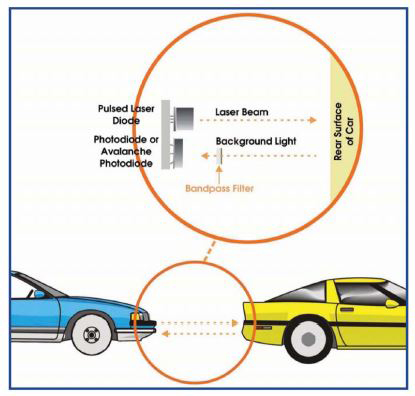
Many applications for pulsed laser diodes are variants of the seminal rangefinding application, in which target distances are calculated by measuring the flight time of laser pulses reflected or backscattered from the target. Using this principle, some of the more sophisticated instruments can make accurate measurements at distances up to 10 km. Police laser “speed guns,” for example, can measure vehicle speed up to 155 mph (250 km/h) at up to 3300 ft (1000 m) with an accuracy of 1 to 3 percent. Unlike conventional radio-frequency speed guns, which measure velocity directly from the magnitude of the Doppler shift in a reflected signal, laser speed guns calculate velocity by comparing distance measurements made at different times.
Since prices came down, eye-safe rangefinders have become available for a variety of recreational activities. Hunters, for example, can buy laser rangefinding devices to measure the distance to their targets with an accuracy of a meter or two over a range of hundreds of meters.
Similarly, golfers can purchase inexpensive laser rangefinders to try to improve their handicaps. In what some (but not all) might consider a less frivolous application, automotive engineers are developing rangefinders based on pulsed laser diodes, to warn drivers of hazards. Laser range sensors are also widely used.
Pulsed laser diodes provide the optical signal in automotive collision-avoidance systems, used as navigational aids for ships, particularly in ports and harbors; in ceilometers for cloud-based measurement at airports; and in surveying and construction.
In a laser safety scanner, pulsed laser diodes create a curtain of light around potentially dangerous areas such as automated production lines. Using coded pulse emission, two-dimensional curtains can be monitored to distinguish between allowed and not-allowed shapes. The high peak power from pulsed laser diodes, when used in combination with avalanche photodiodes, provides the sensitivity necessary to discriminate between shapes. Besides serving as a safety interface, such equipment may also provide remote management and diagnostic functions. Increasingly, similar systems are being deployed on intelligent highways to regulate flow and to identify vehicles at toll booths.
In addition, significant research supports the dramatic wound-healing ability of pulsed laser diodes in medical applications such as laser acupuncture and therapy. Wavelengths in the spectral range of 625 to 905 nm are favored here. The latter wavelength penetrates deeply into tissue and bone to alleviate pain, swelling and inflammation in joints, as well as other afflictions. The laser light must be pulsed to achieve the power necessary for penetration and absorption without damaging the cells.
Generation of short, powerful pulses using laser diodes represents an enabling technology for a variety of applications that cannot be addressed with CW laser diodes, for either technical or economic reasons. Laser Components and other manufacturers have developed commercial products and offer devices at 850, 905 and 1550 nm for such applications with a wide range of output powers and emitting areas, both as single emitters and as stacked devices.
The Model 685 allows you to directly control the pulsed laser diode or to indirectly control it using an electro-optic or acousto-optic modulator.
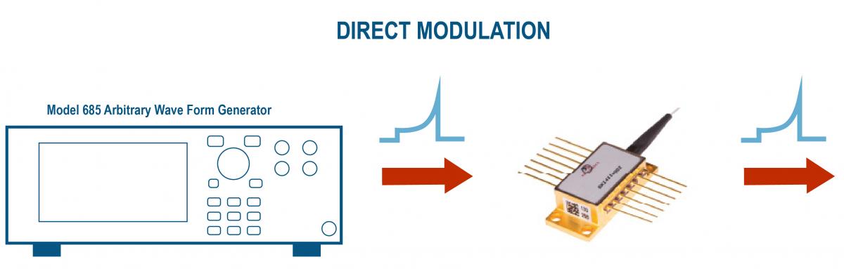
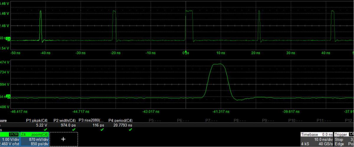
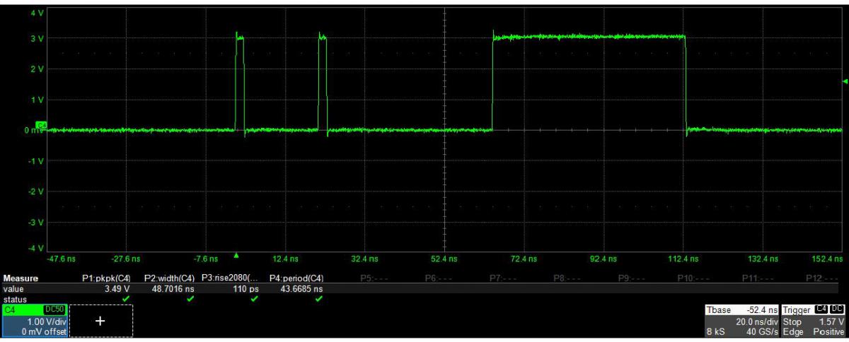
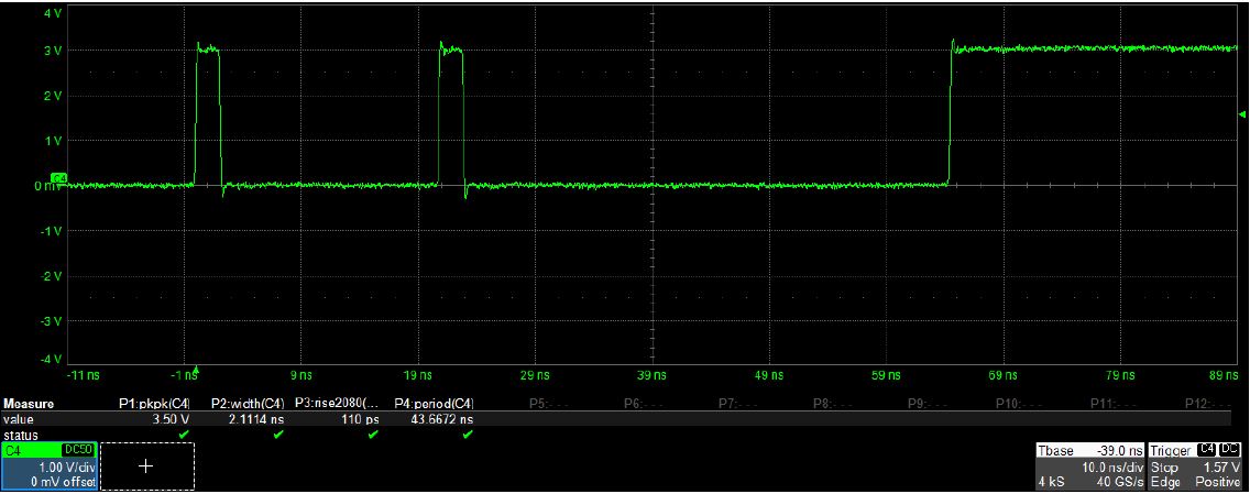
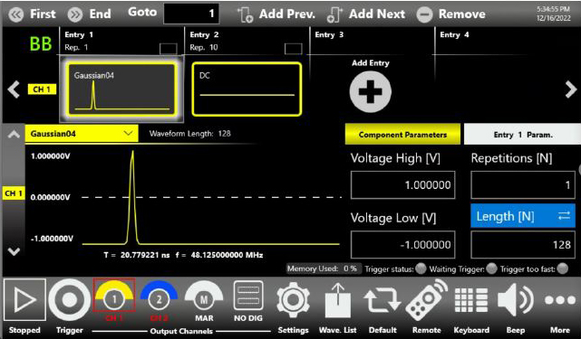
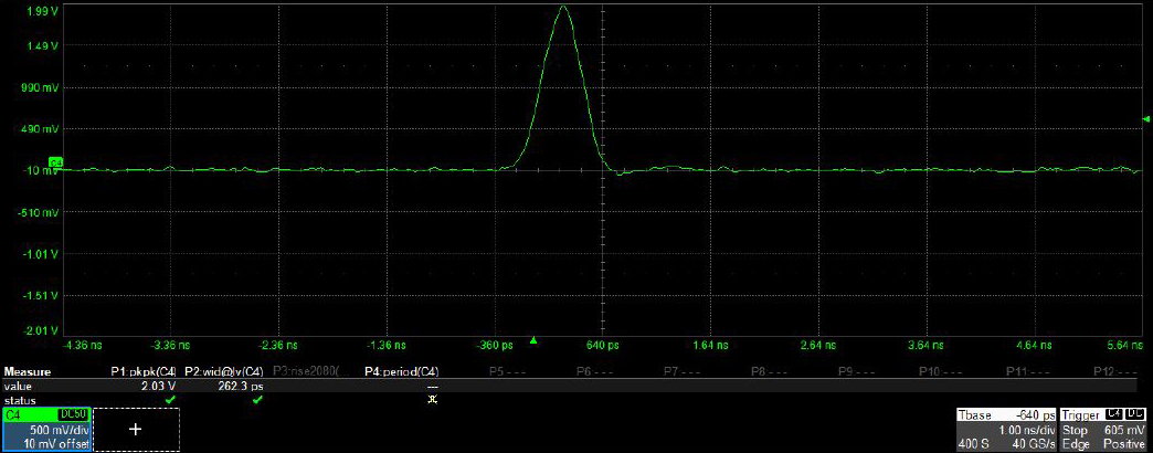
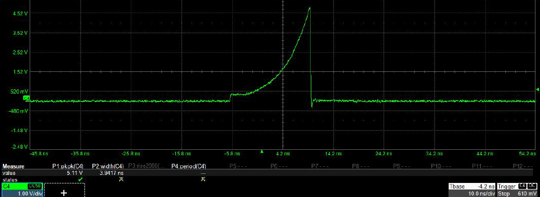
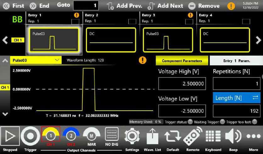
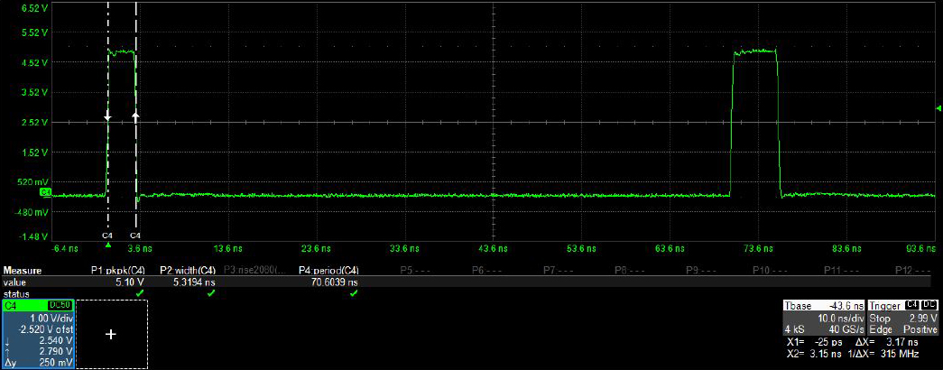
The pulsed laser diodes need to be driven with high amplitude and very short and narrow pulses: the Model 685 can create rectangular, gaussian, exponential shape pulses with an amplitude up to 5Vpp, 110 ps of rise and fall time and a minimum pulse width of 230 ps. The following screenshots testify the possibility of easily creating the different pulses with True-Arb UI and then reproducing them through an oscilloscope.
Conclusion
TheModel 685 provides an extremely flexible and high performance solution to generate all types of pulses or signals that are needed to meet today’s challenges in quantum optics, photonics and laser applications.
The new industry’s requirements and the development of new products, increase the demand for cutting-edge test-equipment instrumentation to satisfy the most demanding applications and the latest scientists’ ideas.