
June 28th, 2022 - How Do I Measure a HV Pulse?
When we want to measure high voltage pulses, the test instrument of choice is usually the oscilloscope, or “scope”. It displays voltage as a function of time, so it’s an excellent tool for examining pulse characteristics such as amplitude, rise time, width, repetition rate, distortion, and so on.

The Need for Speed
Before grabbing just any scope and probe, let’s consider some important specifications.
The scope and the probe together make up a measurement system. Of major importance is the system’s bandwidth in megahertz (MHz) because a higher bandwidth system renders a more accurate waveform on the screen. The rule for good image fidelity is to have a bandwidth of five times the highest frequency to be measured.
Admittedly, we don’t need a high-bandwidth system to simply verify the presence of the pulse train. For example, the maximum pulse repetition rate of a PVX-4150 is 240 kHz, a frequency low enough to be easily displayed on nearly any scope.
But if we want to, say, check pulse rise time, we’ll need more bandwidth. For example, pulses from a PVX-4150 can have a rise time of 25 ns, which translates to a frequency of:
f = 1/T = 1/(2.5 ⦁ 10-8) = 40 MHz
Using the 5X rule, the bandwidth of the scope (and the bandwidth of the probe) should be 200 MHz.
Another pulser, the PVM-1001, has a faster rise time specification (10 ns). In that case we would use a 500 MHz scope and probe to get an accurate pulse picture.
Probe Voltage Rating
Another major issue is the probe’s voltage rating. Is it sufficient? A common passive probe may be rated at 200 V peak in the 1X position and 600 V peak in the 10X position. This is a breakdown rating and we need to avoid getting close to that voltage. It’s also too low for most HV pulser applications. What to do?
One thought might be to temporarily turn down the pulser output voltage so the waveform can be checked with a standard probe. Unfortunately, that idea doesn’t work very well when using a high voltage pulser to drive very low voltage pulses into a high-impedance capacitive load. (Due to the way the switching devices work, the low voltage increases the impedance mismatch, plus transients can be coupled to the output.)
External Divider
Another thought might be to build an external voltage divider, although this should be approached with caution. The usual safety issues must be considered when building anything associated with high voltage. Further, we need to select components that can withstand high voltage without breaking down. And since we’re dealing with very fast edges and their accompanying high frequencies, we need to reduce the parasitic inductance and capacitance of the circuit as much as possible to get an accurate representation on the scope.
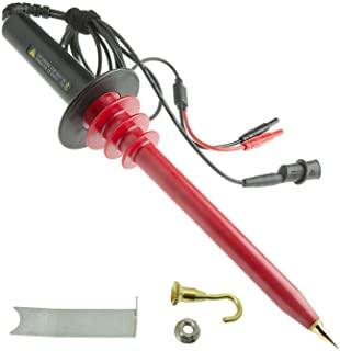
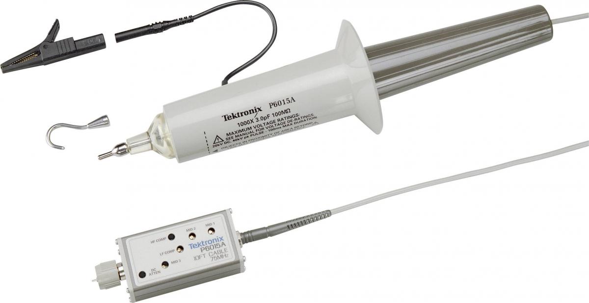
High Voltage Probes
|
|
A high voltage probe is commonly used for the kinds of applications we’re discussing. But before grabbing the closest one, let’s again review specifications. Some HV probes are intended for DC and low-frequency (50/60 Hz AC) measurements. They’re inexpensive but the narrow bandwidth means they’re not capable of being used to view pulses. |
|
|
What we need is a high voltage probe with the necessary bandwidth as discussed previously. Checking the manufacturers’ datasheets, we find a number of models with varying combinations of voltage rating and bandwidth. With rising voltage and rising bandwidth comes a fast-increasing price tag. |
Duty Cycle Limitation
There’s an additional limitation that comes into play with high voltage probes: duty cycle.
When a high voltage probe is used to make pulse measurements, its peak voltage may have to be derated based on duty cycle and pulse duration due to heating. Since this specification is not always evident, be sure to check it on the spec sheet. If the duty cycle of the pulse you are monitoring exceeds the specification, the probe may overheat and become seriously damaged.
Voltage Monitor
A good idea is to simply use the pulser’s VMON (voltage monitor) output. A coaxial cable with BNC male connectors on both ends connects the pulser’s VMON output to the scope’s 1 MΩ input. The pulser provides a real-time signal at a scale factor dependent on the pulser model and found in the datasheet. For example, the voltage monitor scale for the PVX-4110 and PVX-4130 is 2000:1; for the PVX-4140 and PVX-4150 it’s 1000:1. That means for a PVX-4110, the scope displays 1 V of amplitude for every 2000 V of output pulse voltage.

Measuring Pulse Current
We’ve been looking at the requirements for examining the pulse voltage waveform, but what about the current waveform?
A large current flows briefly when we charge the load capacitance, and flows again in the other direction when we discharge it. These currents coincide with the pulse rise and fall times and have durations of a few tens of nanoseconds at most. On a scope they look like very narrow alternating positive and negative spikes. Generally, the current waveform isn’t a critical item to view.
Current Monitor
For applications requiring a view of the current, pulsers such as the PVX-41xx series have an IMON (current monitor) output. A coaxial cable with BNC male connectors on both ends connects the pulser’s IMON output to the scope’s input. The scale factor depends on the model and is found in the datasheet. For the PVX-4150, for example, it’s 10 A/V into 50 Ω. That means each volt of the waveform corresponds to 10 A of output current. The scope input impedance must be set to 50 Ω (or a 50 Ω terminator must be used).
Other Methods
Can you measure the current with a current probe and oscilloscope? Yes, but such probes are expensive because they have a difficult job. Most use a special ferrite material that doesn’t saturate at high currents, yet has a very fast response. A garden-variety current probe cannot be trusted for high-speed measurements.