
February 15th, 2022 - Pitfalls of Using a Pulse Generator to Drive a Laser Diode
By: Bob Schmid, BNC Technical Support
Current pulsers used in laser applications must generate very sharp pulses with very sharp rising edges. A high speed, narrow pulse with a fast rise time is paramount when driving laser diodes for ranging and digital communications.
BNC offers a variety of high current pulsers for use with both laser diodes and LEDs. We often get calls from customers who are experts in optics and laser diodes but have less hands-on experience with electronics, and as a result are having trouble getting a high-speed laser pulse to the load. The problem magnifies when they’re using a high speed pulser more than a couple of feet from the laser diode. Our technical support team is always ready to explain what needs to be done and why. We welcome the opportunity to help our customers get the best performance.
When using a current pulser capable of fast rising edges, correct interconnection is everything—especially when dealing with distance.
What Doesn’t Work
If a customer doesn’t understand what is happening on the electronics side, they’ll typically take a current pulser, grab a laser diode, and connect the two using hookup wire, braid, or a chunk of coax, thinking that because these products are ‘high performance’, it will work fine. It doesn’t. The issue is one of physics.
To see exactly what happens when the connection isn’t good, drive the laser diode into a dead short and take a picture of the pulse on the scope. Next, drive it to the wiring and take another picture. Pulse degradation is quite clear. At the very least, edges are rounded off, and at worst that pulse turns into a sine wave, a big jumble of noise.
Better Approaches
If you’re going to send pulses with rise times of less than a nanosecond to a laser diode, the only way to do it properly is to make the connection with stripline* — two copper conductors that are the same width and insulated from each other all the way from the source to the load. Do not use adapters, clamps, clips, connectors, alligator clips, or clothespins. If you use a few inches or at most a couple of feet of stripline to connect the pulser to the laser diode, you’ll achieve the transfer of a nice rising edge pulse. Although this is not necessarily convenient to do, as laser diodes don’t always lend themselves to a wide, flat copper connection, the paragraphs and photos below show several ways to accomplish it.
You may need to send a pulse 30 feet. After 3 or 4 feet, the pulse can be distorted. The 30 feet can be done. However, you can’t send a one-nanosecond rise time pulse that far. If you can tolerate a one-microsecond rise time pulse, 1,000 times slower, that can be done. There is always a tradeoff between the speed of the rising edge and the amount of inductance that can be tolerated.
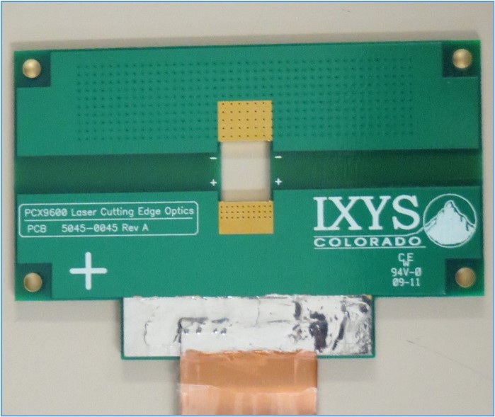
A better approach is to lay out a simple two-layer PCB that adapts the stripline to the laser diode. One conductor of stripline is soldered to each side of the board,  turning the board into an extension of the stripline.
A radial-leaded diode can be mounted perpendicular to the board, while an axial-leaded diode can straddle the edge of the board. It’s easy to design holes or cutouts in the board to match the laser package. Separate boards can be inexpensively produced to interface each package type to the stripline.
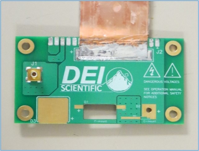
If desired, a DB-37 connector can be added to make it easy to connect and disconnect boards from the stripline. The board layout on the right supports both connection methods.
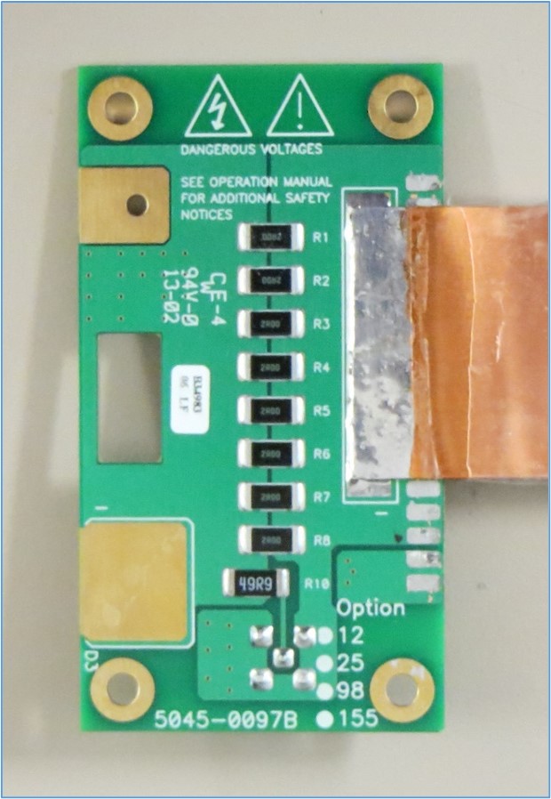
The board shown on the left serves a dual role of interfacing a laser diode to a stripline and providing current monitoring. Here, there are eight parallel-connected 2512-size SMT resistors, chosen for low inductance. The group of eight resistors is connected in series with the pulse output. For example, a 49.9-ohm resistor is connected in series with the current monitor output to match a 50-ohm oscilloscope input.
If the factory-supplied stripline is longer than needed, it can be shortened without ill effect. Do not, however, extend the stripline. Bending it is acceptable, if the conductors are not separated, as separation increases inductance. Keep the stripline away from other conductors.
A Quick Tutorial
People expect pulses to go faster all the time. If light pulses can race down fiber at gigahertz speed, why can’t we get the same speed with a pulser? The difference is that when you’re sending pulses down a fiber, you’re talking microwatts—very low power. Try doing that at 100 amps—it can’t be done. While our pulsers are state of the art, inductance is still the challenge when we talk about sub-nanosecond rise times. Transistors, components, the PCB layout, and the stripline all must be at low inductance so that we don’t modify the pulse from the desired shape. Unfortunately, the situation changes when you want amps.
For a short tutorial on optimizing connections between a high-speed laser diode driver and a laser diode, watch our Making Connections video, below.
BNC offers various models with outputs from 1 mA to 450 A, predominantly used to drive, test, and characterize laser diodes and LEDs. If your application involves either testing insulation/dielectric materials, or driving deflection plates, piezoelectric transducers, or other high-impedance loads, refer to our line of high voltage pulsers. We also offer an online course on High Voltage, High Current Pulsers along with many other topics.
*different from stripline used in microwave applications.