RF designers often find themselves working on input power matching their circuits to a 50-Ohm signal source. The goal of this task is to develop a matching network that delivers most of the input power to the device. For that, the matching network is optimized such that the reflection coefficient presented by the network to the signal source is low (typically <-10dB return loss) over the required frequency range.
RF designers who are working on low-noise amplifiers are also interested in minimizing noise figures of their designs, which, in other words, means increasing the sensitivity of their systems. Can the same input matching network do both: make input reflection coefficient low and minimize noise figure?
To answer this question, one needs to know the noise parameters of their circuit before matching is applied. What are the noise parameters? Noise parameters describe the auto -and cross-correlation between input and output noise waves (or voltages or currents) generated by the devices. The most general way of representing this is by using noise correlation matrices. However, in practice rather than using such matrices, noise parameters are used. The noise parameters give the same information but arguably in a more intuitive manner.
There are different ways the noise parameters are formulated. Minimum noise factor, Fmin, is one such noise parameter. Sometimes it is replaced with its dB representation, minimum noise figure, NFmin, and sometimes it is described with the minimum noise temperature, Tmin, where Fmin=1+Tmin/T0 and T0=290K is the reference temperature. T0=290K is not exactly a typical laboratory temperature but it is close and, when multiplied by Boltzmann’s constant, produces 4×10-21 that is easy to work with, especially when one only has a slide rule to do the analysis with…
Fmin indicates the absolute lowest noise factor a device can achieve at a given operating point (supply voltage and current), frequency and temperature.
The information on how to achieve Fmin comes from another noise parameter, Γopt, which is the optimum reflection coefficient of the signal-source that results in Fmin. Γopt can also be rewritten in terms of the optimum impedance, Zopt, or the optimum admittance, Yopt.
If the matching network transfers the input impedance of a device to be conjugate of the signal-source impedance and also transfers the signal-source impedance to Zopt as seen by the device, then the device is both power matched and noise matched. If, however, this matching network cannot achieve Zopt and instead creates Zs≠Zopt, then the device noise factor will be larger than Fmin.
How much larger? The amount of increase of the noise factor due to mismatch depends on the last noise parameter. Often, the equivalent noise resistance, Rn, is used to represent this noise parameter. With Rn, the noise factor expression of the device can be written as
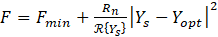 ,
,
where Ys=1/Zs, Yopt=1/Zopt, and  is the real part of Ys. The noise factor can also be written as a function of reflection coefficient as
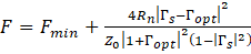 ,
,
where conventional conversion from impedances to reflection coefficient

is used in which Z0 is the characteristic impedance, typically 50 Ω.
A designer, who is familiar with network analysis in terms of traveling waves, S-parameters, and reflection coefficients, may find the last expression of noise factor atypical. Particularly, the “+” sign, as in  , is not very common. Also, a designer, who wants to re-analyze the noise parameters after a short interconnecting line is added at the input, would find that adjusting the phase of
  based on the transmission line length is straight forward, Fmin does not change, but Rn does and in a not straightforward fashion.
While Rn is commonly used, it is not a fundamental noise parameter. A much better noise parameter is Lange invariant parameter N. Why N is a better noise parameter? First, like Fmin, N does not change when the device is embedded in a lossless passive network. In the example above, the short interconnect at the device input would keep both N and Fmin unchanged. Second, N permits a check of noise parameter measurement accuracy. It has been shown in the literature that Fmin‑1≤4N has to be true and if noise parameters do not show this relationship, then their errors in their measurements. Third, for many transistors Fmin-1≈2N. This relationship is very convenient for back of the envelope analysis. Fourth, N scales with transistor size in a similar way to Fmin.
Since N, like Rn, shows the sensitivity of noise factor to mismatch between Zs and Zopt or between Ys and Yopt, Rn and N are related. In fact they are related via
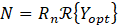 .
.
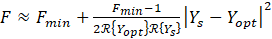
Then, the noise factor can be recast in terms of N as:
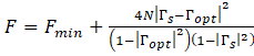
or
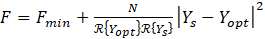 .
.
The noise factor expressions can be simplified as
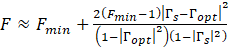
or
and only two noise parameters Fmin and Yopt (or or Zopt).
Whether one adopts Rn or N and whether one simplifies expression for noise factor or not, the measurements of noise parameters stay the same. These can be measured by either a source pull method employing impedance tuners or impedance generators or a long-line method or a six-port method or any other methods.
Written by Leo Belostotski