This application note describes how to use the Model 675 High Performance Arbitrary Waveform Generator to generate the signals for the test and design of Ultrasonic MEMS sensors.
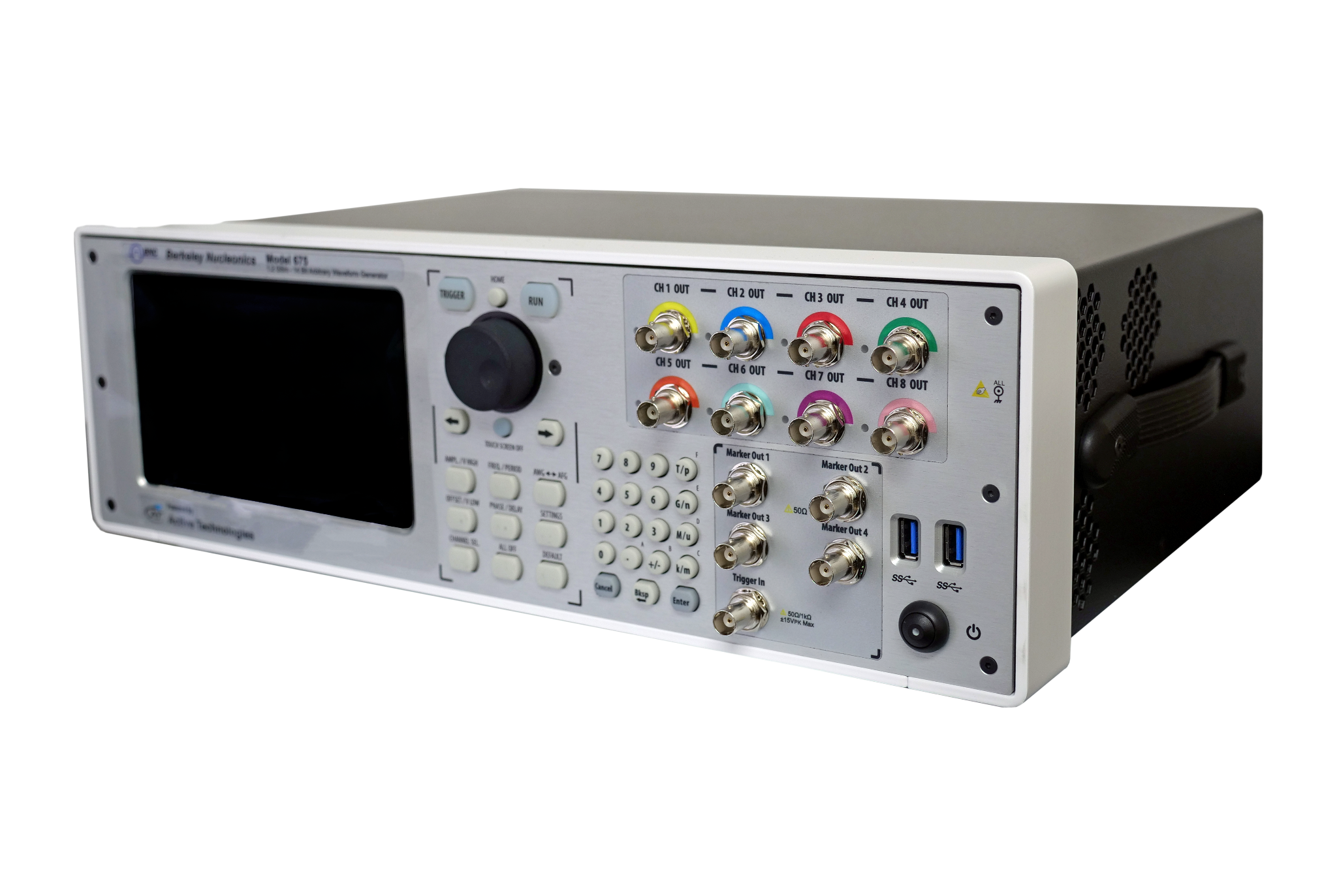
The Model 675 High Performance AWG simplifies the generation of pulse and chirp signals typically used to perform design tests and characterize MEMS sensors. Considering the amplitude of 24 Vpp into High-Impedance (12 Vpp into 50 Ohm) joined to an analog shift of ±12V into High-Impedance, the Model 675 represents the ideal solution for these kinds of tests where high voltage amplitude, programmable pulse’s width, and rise/fall time are mandatory.
-
Accelerate testing, reliability, characterization, and failure analysis of ultrasonic MEMS sensors.
-
Reduces the time to generate complex train pulse scenarios.
General Considerations About MEMS Sensors
MEMS (Micro-Electro-Mechanical Systems) sensors leverage silicon’s unique mechanical properties to integrate mechanical structures able to sense acceleration, rotation, angular rate, vibration, displacement, heading, and other physical and environmental properties. Those considerations, united to an analog front end with an excellent harmonic distortion, produce a circuit that combines electrical circuits and 3-dimensional mechanical structures.
Nowadays, MEMS sensors and microphones are widely used in many applications starting from distance and motion detection, mobiles, IoT, drones, automotive, pressure measurements, and humidity and temperature sensing, to name a few.
Main Types Of MEMS Sensors
-
Accelerometers
-
Gyroscopes
-
Digital E-Compasses
-
Inertial Measurement Units (IMU)
-
MEMS Microphones
-
Pressure Sensors
-
Temperature Sensors
-
Proximity Sensors
-
Humidity Sensors

Applications
Ultrasonic Sensors For Distance Measurement
To reduce the spread of COVID-19, offices and factories are being required to create an environment in which social distancing between workers and safe work practices are ensured.
Distance measurement is as accurate as less than 1 cm for ultrasonic sensors and less than 10 cms for UWB, compared to several meters for BLE, which is not enough to detect two people as they approach the recommended safe distance of approximately 2m. The ultrasonic transducer mounted on the sensor transmits an ultrasonic pulse and receives a wave reflected back from the object. Using this Time-of-Flight (ToF), the distance from the object can be accurately detected.
Ultrasonic MEMS For Industrial And Automotive Applications
Industrial applications include precision agriculture, construction machinery, drones, automatic guided vehicles (AGVs), robots, and industrial motors. Motion sensor data has become critical in enabling automation, improving efficiency, and monitoring conditions in these industrial applications.
MEMS accelerometer products deliver the precise motion, vibration, and inclination measurements that these applications need.
Regarding automotive, MEMS sensors can be used for a wide range of applications from dead reckoning, vehicle to vehicle location, vision systems, augmented reality, liftgate control, and telematics to in-vehicle infotainment and smart antennas.

MEMS Barometric Pressure Sensors
The latest barometric pressure sensors use innovative capacitive MEMS architecture to deliver lower power consumption and noise than competing technologies.
These MEMS can measure a height change as small as 5 cm, less than the height of a single stair. As a result, they are best suited for smartphones, tablets, wearables, drones, and many other devices to determine the accurate location of emergency calls, track changes in elevation for activity monitoring, support indoor or 3D navigation, and other motion- or position-based services.

Signal Generation For MEMS
Ultrasound Medical Imaging Applications
Ultrasound imaging has gained much interest in the medical field due to its less harmful characteristic to the human body compared to other well-known methods, such as magnetic resonance imaging, computed tomography, and X-rays.

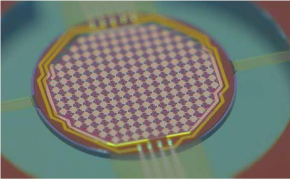
In addition, the emergence of Capacitive Micromachined Ultrasound Transducer (CMUT) device technology over the last decade has propelled interest even further. Compared to its piezoelectric counterpart, the CMUT provides the advantage of a wider operational bandwidth and a simpler fabrication for large array implementations.
The HV output pulse driver and the level shifter adopt a multiple-stacked architecture with a dynamic gate biasing circuit to generate an over 10 Vpp pulse signal at a 1.25-MHz frequency while driving the CMUT device immersed in an oil environment.
The pulse width, the period, and the required amount of generated acoustic pressure, which relates to the maximum voltage of the output pulse signal, are decided at a system level, depending on the specific medical imaging application, as well as the device characteristics of the following transducer.
The CMUT-mounted PCB is placed in a glass container filled with vegetable oil to mimic an underwater environment, while the IC-mounted board is placed outside. A hydrophone is placed a few millimeters from the CMUT to measure the resulting transmitted acoustic pressure and convert it to a voltage signal.

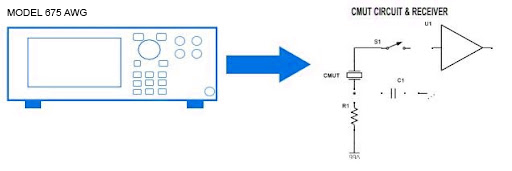
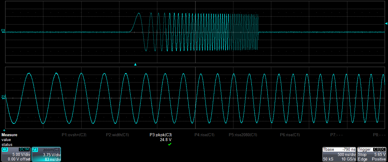
Usually, an external arbitrary waveform generator is needed during the design stage to generate an input pulse of 10Vpp to drive the CMUT at the output.
A specific medical imaging application needs signals with different amplitude levels: The CMUT converts the electrical signal to an acoustic pressure signal corresponding to the amount of applied voltage.
The BNC AWG generators have unmatched voltage swing capability combined with a hardware offset feature: The 12 V pp (50 Ω into 50 Ω) amplitude range and the ±6 V (50 Ω into 50 Ω) hardware offset voltage offer a total voltage window of 24 Vpp into 50 Ω or 48 Vpp into High-Impedance.


All of the pulse parameters can be changed on the fly without glitches using the Arbitrary Function Generator mode: You can control in real-time the pulse width, rise and fall time, period, delay, and amplitude.


Multi-Level Pulse For Medical Imaging Applications
A two or three-level pulse is presented for medical ultrasound imaging applications, particularly those using capacitive micromachined ultrasonic transducers (CMUT).
The pulser employs a bootstrap circuit combined with dynamically biased stacked transistors, which allow for HV operation above the process limit without lowering the device’s reliability.
Medical ultrasound imaging has significantly impacted clinical practice by providing real-time images of different organs with a high spatiotemporal resolution, non-invasively and at a low cost. In recent years, Capacitive Micromachined Ultrasound Transducers (CMUT) have shown several advantages over the conventional bulk piezoelectric transducers due to their smaller size, wider bandwidth, and ease of integration with interfacing circuitry. However, compared to piezoelectric transducers, CMUTs typically have larger electrical impedances for the same transducer area.
An ultrasound pulse generator is one of the critical building blocks of medical ultrasound imaging systems, which drives the ultrasound transducers, including CMUTs, with a high voltage (HV) output swing to create an ultrasonic pressure pulse towards the target tissue.


The BNC Waveform Editor tool allows you to create multi-level pulses that are key in this application easily. In addition, it is also possible to add noise and/or filters to simulate a real-life environment.


Security of Ultrasonic Sensors For Autonomous Vehicles
The automotive industry is one of the most promising sectors for the Internet of Things (IoT). Self-driving technologies are built on modern sensors that enable vehicles to monitor the driving environment by themselves. Therefore, the reliability of the sensors determines the safety of self-driving vehicles.
These sensors are widely used on IoT devices for ranging and occupancy detection, which corresponds to two scenarios on a vehicle:
-
Parking when a car is traveling at low speeds.
-
Detecting blind spots at high speeds.
Sensors should detect all present obstacles and avoid false alarms, and vehicles should handle the following two scenarios correctly.
-
Stop With Obstacles: A vehicle should stop moving toward obstacles in the driving path and avoid active collisions.
-
Keep Moving Without Obstacles: A vehicle should keep moving when there are no obstacles in the driving path and prevent passive collisions with unprepared traffic.
It is possible to simulate the attacks on stand-alone ultrasonic sensors in the laboratory and the onboard sensors of several vehicles outdoors during the design stage.
By transmitting over-the-air signals created using an Arbitrary Waveform Generator, it is possible to create different attacking scenarios to simulate the following situations:
-
A Vehicle Stops When It Should Keep Moving: We trick the onboard ultrasonic sensors into reporting non-existing obstacles anywhere within the detection range by designing two types of spoofing attacks — random and adaptive spoofing.
-
A Vehicle Keeps Moving When It Should Stop: The design choices of ultrasonic sensors make it possible to hide obstacles. For example, a jamming attack or an adaptive spoofing attack can both prevent sensors from reporting an obstacle on the road.
Ultrasonic sensors were first introduced into automobiles as sensors of parking assistance systems in the early 1990s.
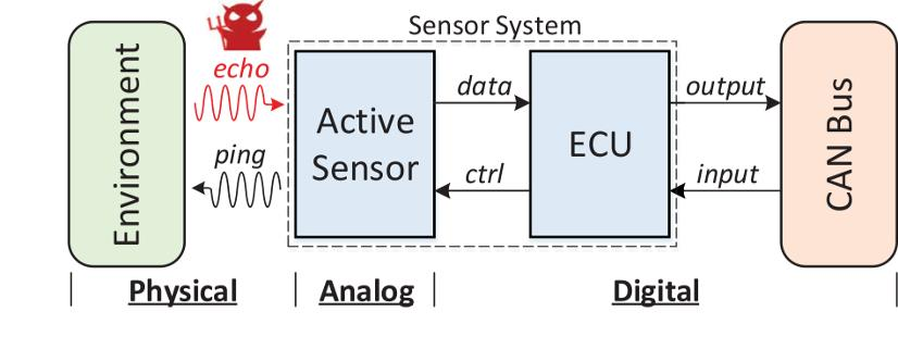
Attack Scenario: The adversary can eavesdrop on the physical signals from onboard sensors and actively generate forged echoes in an arbitrary form (frequency, amplitude, duration, phase, etc.), thereby corrupting or overpowering other concurrent physical signals in propagation.
Attack Types
-
Spoofing Attacks: Spoofing attacks involve emitting carefully crafted signals (e.g., ultrasound pulses) identical to those transmitted by the sensors, i.e., with the same frequency, modulation, etc. As a result, the sensors may interpret the spoofing signals the same way as authentic signals and falsely detect non-existing obstacles. In addition, by carefully adjusting the timing of the spoofing signals, an adversary may “create” fake obstacles at various locations of their choice.
-
Jamming Attacks: Jamming attacks involve injecting similar but stronger signals to overpower the real ones. Sensors are typically designed to be robust against benign ambient noises, but they hardly expect strong interference. As a result, it is unclear whether sensors can detect objects in the presence of jamming attacks. Furthermore, if the interference is so strong that it causes sensor denial-of-service, it is also unclear whether sensors and automobiles will fail gracefully and not cause fatal accidents.

Building a Random Spoofer: We acquired ultrasonic transducers with the same operating frequencies as the target sensors to validate spoofing attacks. To drive the transducers, we utilize off-the-shelf hardware that can be an Arbitrary Waveform Generator.
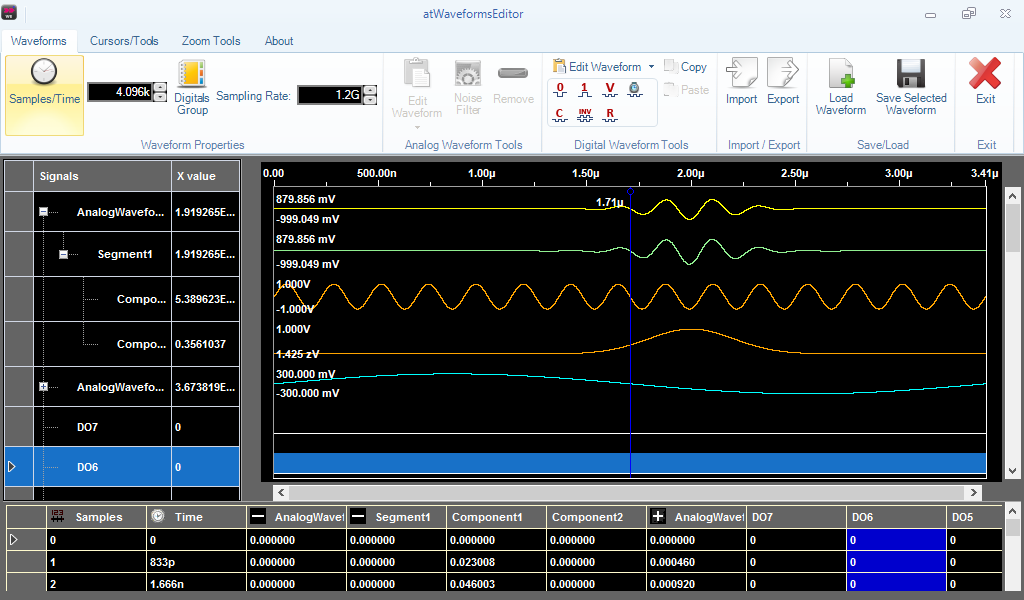
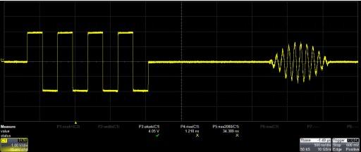
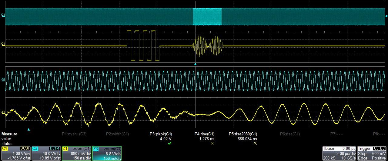
The picture below represents the sequencer of the 675 AWG Series that has been loaded with a train of pulses, a DC-level that acts as a pause, and an echo that is the response of the ultrasound.
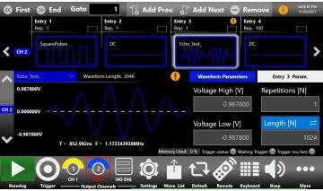


The Model 675 AWG has a built-in Gaussian random noise generator that can add noise to your signal to emulate the response of the ultrasound sensor in a noisy environment or to simulate the interaction between the returning signals and the environment.
The Waveform Editor software package allows you to create very complex analog and digital waveforms easily; moreover, it is possible to add noise and filter features to the signal you are editing.

Jamming Attacks
Jamming attacks generate ultrasonic noises that induce continuous vibration on the sensor membrane and render distance measurement impossible.
Voltage Level: The amplitudes of sounds created by piezoelectric crystals rely on the voltage level of the signals that drive the crystals. Thus, the effective jamming distance is determined by the applied voltages.
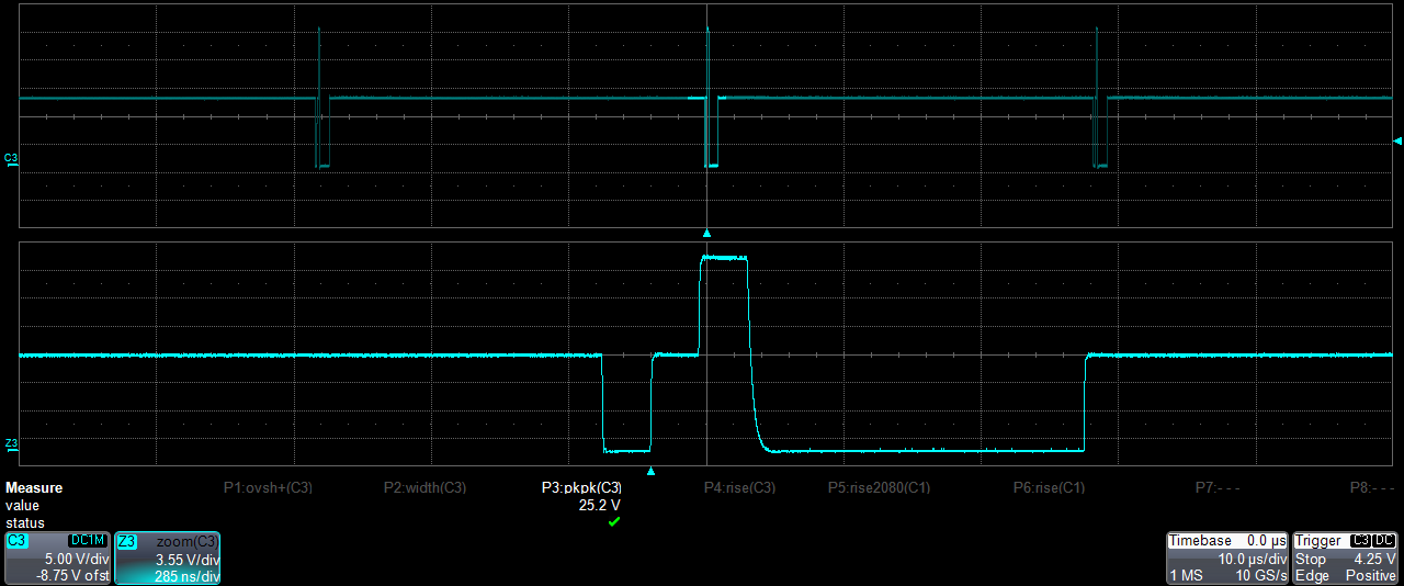
The Model 675 AWG can generate square pulses up to 24 Volts into High-Impedance.

Ultrasound Communication And Range Finder Systems For Sensors
Ultrasonic time-of-flight (ToF) sensors are commonly recognized as the best range-sensors for automotive and industrial applications — as well as for drones and robotics, as they offer numerous advantages over optical or infrared sensors. For example, they deliver the most accurate range measurement regardless of target size or color, are immune to ambient noise, and work in direct sunlight. For these reasons and because they are robust, accurate, and reliable, ultrasonic sensors are widely used in industrial and automotive applications.
MEMS-based ultrasonic sensors offer the same performance and reliability as conventional ultrasonic sensors but with a form-factor up to 1,000 times smaller and with a power consumption up to 100 times lower than conventional ultrasonic sensors. These miniature sensors are small enough to enable the entire spectrum of ultrasonic sensing in compact consumer applications, such as smartphones and wearables.
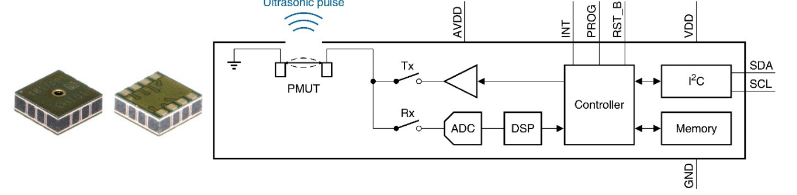
The sensor measures range by emitting an ultrasonic “chirp” and then listening for echoes returning from targets in the sensor’s field of view. Each echo travels at the speed of sound, and an echo’s time of flight provides a precise measure of the distance to a corresponding target.

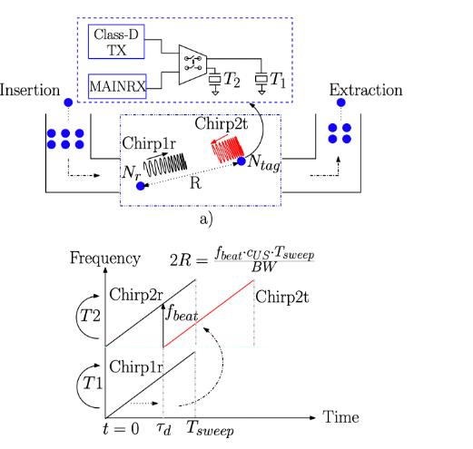
Instead of transmitting the signal with a linearly increasing frequency in time, a chirp with a sawtooth (up and down) frequency change in time should be used to estimate the relative distance and velocity of the nodes.
The conventional FMCW method uses the echoes reflected from objects in the environment and provides a distance measurement method for these objects. In addition, this method could be adopted for distance measurement in the go-with-the-flow approach. In this case, each node in a swarm would perform the distance measurement independent from the other. Thus, no synchronization would be needed.


Ultrasound MEMS For Damage Detection In Concrete
Nonlinear ultrasonic techniques have been developed over the last decades to detect the presence of damage in materials of interest in the field of civil engineering, such as concrete or mortar.
High-resolution ultrasound waveform generation combined with high voltage signals allows for detecting small variations in the sample microstructure and, therefore, is more adapted to detecting the presence of small cracks or damaged areas concerning traditional linear ultrasonic techniques.
Slow Dynamics
The excitation was applied to one end of the sample using the Model 675 High Performance AWG. The temporal response signal was detected at the other end using a digital oscilloscope for data acquisition. The signals were recorded in a short time window once stationary conditions were reached.

Fast Dynamics
The same sample and experimental set-up were also used to consider fast dynamics effects. However, in this case, the protocol for the source amplitude variation was different. The signal amplitude at the edge is proportional to the strain amplitude in the sample since we are exciting compressional waves. Results show a softening of the material and an increase of attenuation with increasing strain, in agreement with observations in the literature for similar samples.
Conclusions
Ultrasonic MEMS sensors can address a wide range of applications, and they are becoming very popular these days. As a result, semiconductor and digital imaging companies are investing money and research time into this market segment; the market forecast is approximately 6 billion USD by 2025.
The Model 675 High Performance AWG Series represents a key component for designing, testing, and characterizing next-generation Ultrasonic MEMS and components.