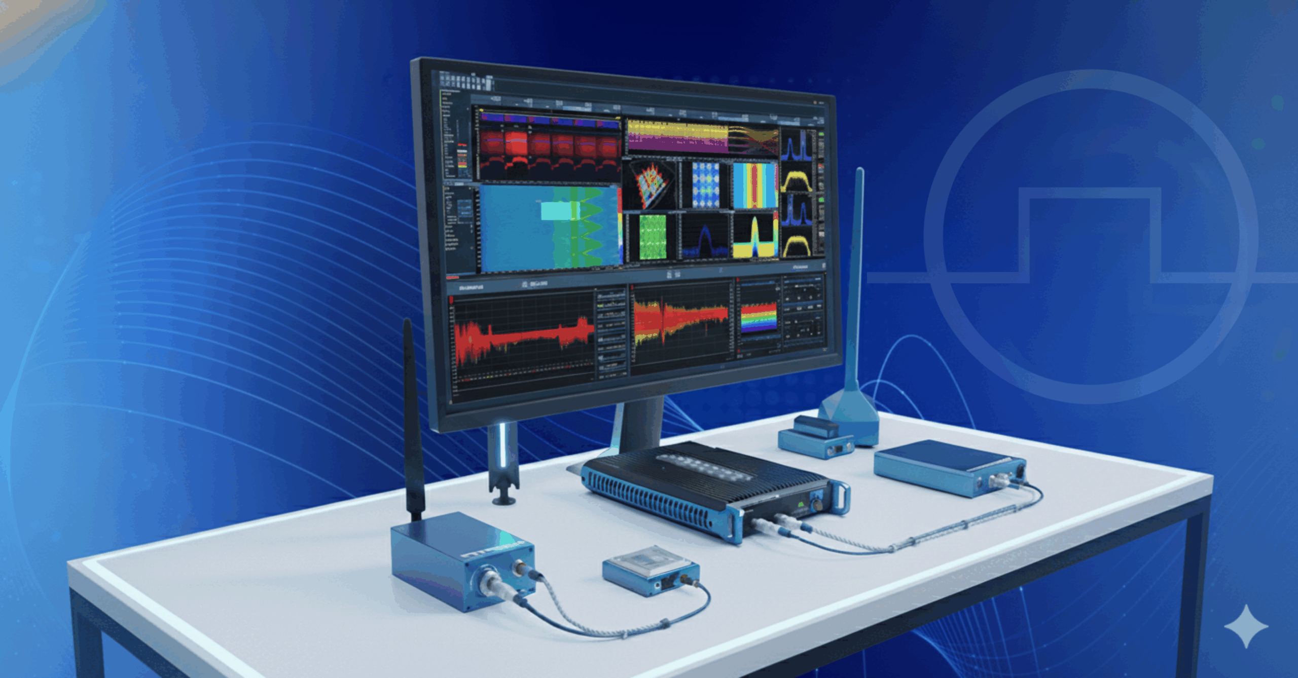
Introduction:
It is a great treat to learn about the ways in which our equipment from Berkeley Nucleonics has improved applications, driven solutions, and provided answers for research teams at some of the most decorated institutions across the world. Most recently, we’ve touched base with a researcher at the Facility for Rare Isotope Beams (FRIB) following their purchase and use of the PVX-4141 bipolar pulse generator to be involved in the design and subsequent testing of a fast machine protection system and chopper monitor system.
In the case of this particular operation, PVX-4141 is tested for use in a linear accelerator to verify that our bipolar pulse generator works fast enough for the intensive operations at FRIB. Spoiler alert: it does. Read through the quick synopsis here to find out what this type of rigorous unit testing entails from its beginning concepts to its conclusion. Or, navigate to FRIB’s published article, linked [here].
Design:
The design of the system is relatively common. The IOC/OPI is the user interface. The user can set threshold values, different beam modes, and verify that each element of the system is working as intended.
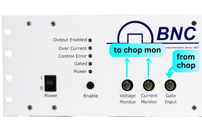
The chopper monitor system takes analog information from the PVX-4141 and other parts of the accelerator systems, digitizes them, and performs operations using an FPGA to compensate for small changes in the beam in real time. This is done by modulating the frequency and width of the gate signal controlling the PVX-4141 pulse width and repetition rate. In other words, the PVX voltage monitor and current monitor provide data used to maintain stable operation.
Pulse Checker:
The signal from the PVX-4141 is not static. The width and frequency are “ramped” aka slowly increased in a linear fashion in different phases. The pulse checker monitors the ramp rate and ensures it is behaving correctly.
Voltage and Current Monitor:
The Voltage monitor (VMON) and current monitor (IMON) go into the ADC and are processed by the FPGA. The ADC takes in the VMON and IMON signals and converts this to digital information, as explained above. In a quick summary, the FPGA is a computer that performs mathematics on this received digital data.
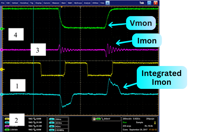
To read the super-fast current pulses, the IMON signal shown in purple is integrated with a capacitor during the rising edge, then reset with the signal shown in yellow before the falling edge, then reset again after the falling edge before the next pulse
This creates a clear, readable signal for the FPGA to measure the current flowing in and out of the plates that accelerate the particle beam.
Test in Beam Line:
The validation results are displayed in image 2. Lets break down the meaning of the results pictured.
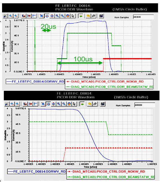
Image sourced from Page 2, chrome-extension://efaidnbmnnnibpcajpcglclefindmkaj/https://accelconf.web.cern.ch/linac2018/papers/tupo007.pdf
The green line is at 1, which means that the beam is started; then the green line is at 3 which means the beam is on.
The red line goes from zero to 1. This means there is a fault, which causes the green line to go to 2 – the beam is stopping. The green line then goes to 0 – the beam is off.
Conclusion:
So, what does this mean? This test has verified that the beam auto-shutdown works and that the time it takes the PVX-4141 to react to the error is short enough to stop any damage from taking place. This paper highlights the 4141’s aptitude for integration in scientific testing and research. This model (as well as the entire PVX line) is already set up in such a way that useful information for automation and real-time feedback is available. This makes it an ideal candidate for use in large complex systems where every aspect must be measured and monitored.