


The BNC Model 645 50MHz Function/Arbitrary Waveform Generator delivers many advanced features and user modes than our previous models, with a price that is designed to meet tough economic constraints. New DDS+ technology embraces advancements in the semiconductor industry and leverages state-of-the-art components for both standard and complex functions. The resulting design is a box for every bench, far more capable than the ARBs and Function Generators of the past. We have even incorporated IP support so a web browser can control the instrument over LAN.
The Model 645 has some significant advances over our 20MHz and 30MHz models. The speed, sample rates, and memory are expanded. The storage of custom waveforms is increased and the tactile front panel controls are easy to manipulate. We understand the broad range of applications and can now provide you, our demanding customers, a product loaded with functionality that represents excellent value. Start your 30 day trial today.
Overview
- 50MHz sine, 10MHz Arbitrary Waveform
- 14-bit, 125MSa/s, 256 K-point ARB
- Pattern Generator (16 bits wide, 256K depth)
- Pulse, Ramp, Triangle, Noise
- AM, FM, PM (PSK), FSK & PWM Modulation
- Linear & Logarithmic Sweeps
- USB, LAN or GPIB Optional programming
- wavePRO Waveform Creation, Editing and Importing
- Nanotechnology, Automotive to Power Industry testing
- Radar, Medical / Biomedical Simulations
- Phase Sync'd signals for MEMS, gyro control
- Count rate Simulation (linear or non-linear)
- Throughput / Response Measurements
- 50MHz ARB with 14 bit, 125M samples/sec, 256K memory
- Display - Illustrates Active Waveform
- Sync - Multiple units together, or to an external clock
- Functions - Square Wave w/ 10nS Risetimes, ramps, triangles, pulses with adjustable edges to 10nS, noise to 20MHz
- Standard Waveforms —Sine, Square, Ramp, Triangle, Pulse, Noise, DC
- Built-In ARB Waveforms — Exponential Rise and Fall, Negative Ramp, Sin(x)/x, Cardiac
- Total Harmonic Distortion —DC to 20kHz, 0.04%
- Square Wave —1uHz to 25MHz
- Modulation Modes - AM, Amplitude Modulation; FM, Frequency Modulation; PM, Phase Modulation; PWM, Pulse Width Modulation; FSK, Frequency Shift Keying
- Pulse Mode Frequency—10MHz
- Pulse Mode Width —10nS res
- Arbitrary Mode Frequency — 1uHz to 10MHz
- Arbitrary Model Length — 2 to 256K
The Model 645 can generate variable-edge pulses at rates up to 10MHz. From the front panel or through remote communications, the user may vary the period, pulse width, and amplitude. The pulse parameters may be stored in the unit or on your computer for later recall. If you have multiple units in your experiment, you may elect to save the setup and upload the pulse properties to multiple Model 645s. For adjustability and routing pulsing tests, see the flexible nature of the Model 645.
Many research activities requiring a variety of custom pulses, the Model 645 allows users to generate complex custom waveforms on a computer and download the waveform properties into the ARB. The custom nature of the device lends itself well to R&D activities with a range of vaiable tests that need to be performed. The Model 645 offers 14-bit resolution and a 125 MSa/s sampling rate, giving users enough control of their waveforms for most applications. The Model 645 will storage of up to 5 waveforms concurrently [4 waveforms (4 x 256K points)] in nonvolatile memory and 1 waveform in volatile memory.
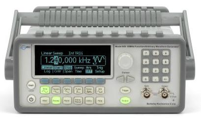
In graph mode, the user can visually verify the signal settings. Also, the user can always see the selected function on the upper left corner of the display.
BNC WaveCrafter allows users to create, edit, and download complex waveforms into their Model 645 quickly and efficiently. Storage of complex waveforms can be done on the PC or emailed among colleagues. In addition, users can retrieve waveforms from a number of Digital and Mixed-Signal Oscilloscope (such as the Agilent MSO 8104) using WaveCrafter in capture mode.
The Model 645 offers users the ability to create and store 16-bit data for later retrieval. The data can be transmitted via a “Pattern Out” from the Model 645 rear panel as a source of control signals for your experiment.
The front-panel operation of the Model 645 is simple and user-friendly. Users can enter setup parameters and access all functions with no more than two button presses. The knob and convenient numeric keypad allow fast setting of frequency, amplitude, offset and other parameters. You may enter voltage values in Vpp, Vrms, dBm or high & low levels. Timing parameters can be entered in Hertz (Hz) or seconds.
Users can easily use the following functions.
- Internal modulations of AM, FM, PM (PSK), FSK & PWM for waveform adjustment.
- Built-in linear and logarithmic sweeps from 1ms to 500 s.
- The burst mode has a selectable number of cycles per period of time.
- Using remote control via USB, LAN or Opt. GPIB interface.
- The programmability by SCPI commands under the remote control connection.
- Precise phase adjustments and calibrations can be done from the front panel or via a PC.
Rather than a traditional mechanical rotary encoder which begins to fail at 25,000 turns, our optically coupled rotary encoder has a life cycle of 1,000,000 turns. Long term reliability is in every detail.
Specifications
| Display | Graph mode for visual verification of signal settings | |
|---|---|---|
| Capability | Standard Wave forms | Sine, Square, Ramp, Triangle, Pulse, Noise, DC |
| Built-in arbitrary waveforms | Exponential Rise and Fall, Negative ramp, Sin (x)/x, Cardiac | |
Waveform Characteristics
| Sine | Frequency | 1 µHz 50 MHz |
| Amplitude Flatness (Relative to 1 KHz) |
0.1 dB (< 100 KHz) | |
| 0.15 dB (<5MHz) | ||
| 0.3 dB (<20 MHz) | ||
| 0.5 dB (<50 MHz) | ||
| Harmonic Distortion (Unit dBc) |
DC to 20 KHz -70 (<1Vpp) -70(≥ 1Vpp) |
|
| 20 KHz to 100 KHz -65 (<1Vpp) -(≥ 1Vpp) |
||
| 100KHz to 1 MHz -50 (<1Vpp) -45 (≥1Vpp) |
||
| 1 MHz to 20 MHz -40 (< 1Vpp) -35 (≥1Vpp) |
||
| 20 MHz to 50 MHz -35(<1Vpp) -30 (≥1Vpp) |
||
| Total Harmonic Distortion | DC to 20 KHz, Output ≥ 0.5Vpp THD+N ≤0.06% |
|
| Spurious (non-harmonic) |
DC to 1 MHz -70 dBc |
|
| 1 MHz to 50 MHz | ||
| -70 dBc + 6dB/ octave | ||
| Phase Noise (10K Offset) |
-115/dBC/ HZ, typical when f ≥ 1MHz, V ≥ 0.1Vpp | |
| Square | Frequency | 1 µHz to 25 MHz |
| Rise/ Fall time | < 10 ns | |
| Overshoot | < 2% | |
| Variable Duty Cicle |
20% to 80% (to 10MHz) | |
| 40% to 60% (to 25 MHz) | ||
| Asymmetry | 1% of period + 5 ns (@ 50% duty) | |
| Jitter | 200 ps when f ≥ 1MHz, V ≥ 0.1Vpp |
|
| Ramp, Triangle | Frequency | 1 µHz to 200 KHz |
| Linearity | < 0.1% of peak output | |
| Symmetry | 0.0% ~ 100.0% | |
| Pulse | Frequency | 500 µHz to 10 MHz |
| Pulse Witdh | 20 ns minimum | |
| 10 ns res. (period ≤ 10s) | ||
| Variable Edge Time | <10 ns to 100 ns | |
| Overshoot | < 2% | |
| Jitter(RMS) | 200 ps when f ≥ 50KHz, V ≥ 0.1Vpp |
|
| Noise | Bandwidth | 20 MHz Typical |
| Arbitrary | Frequency | 1 µHz to 10MHz |
| Length | 2 to 256 K | |
| Resolution | 14 biys (Including sign) | |
| Sample Rate | 125 MSa/ s | |
| Min Rise/ Fall | 30 ns typical | |
| Linearity | < 0.1% of peak output | |
| Settling Time | <250 ns to 0.5% of final value | |
| Jitter (RMS) | 6ns + 30ppm | |
| Non-Volatile Memory | 4 waveforms * 256K points |
Common Characteristic
| Frequency | Resolution | 1µHz |
| Amplitude | Range | 10mVpp to 10Vpp in 50Ω |
| 20mVpp to 20Vpp in Hi-Z | ||
| Accuracy (at 1KHz) |
±1% of setting ±1mVpp | |
| Units | Vpp, Vrms, dBm | |
| Resolution | 4 digits | |
| DC Offset | Range (Peak AC + DC) |
±5V in 50Ω typical |
| ±10V in Hi-Z | ||
| Accuracy | ±2% of offset setting ±0.5% of amplitude setting |
|
| Resolution | 4 digits | |
| Main Output | Impedance | 50Ω typical |
| Isolation | 42 Vpk maximum to earth | |
| Protection | Short-circuited protected; overload automatically disables main output |
|
| Internal Frequency reference Accuracy | ±10ppm in 90 days | |
| ±20ppm in 1 year | ||
| External Frequency reference | Standard/ Option | Standard |
| External Frequency Input | Lock Range | 10 MHz ± 500 Hz |
| Level | 100 mVpp ~ 5Vpp | |
| Impedance | 1KΩ typical, AC coupled | |
| Lock Time | < 2 sec | |
| External | Lock Range | 10 MHz |
| Frequency Output | Level | 632mVpp (0dBm), typical |
| Impedance | 50Ω typical, AC coupled | |
| Phase Offset | Range | -360° to 360° |
| Resolution | 0.001° | |
| Accuracy | 8 ns | |
Modulation
| Modulation Type | AM, FM, PM, FSK, PWM, Sweep and Burst | |
| AM | Carrier | Sine, Square, Ramp, Arb |
| Source | Internal/ external | |
| Internal Module | Sine, Square, Ramp, Triangle, Noise. Arb | |
| Frequency (Internal) | 2mHz to 20KHz | |
| Depth | 0.0% ~ 120.0% | |
| FM | Carrier | Sine, Square, Ramp, Arb |
| Source | Internal/ external | |
| Internal Modulation | Sine, Square, Ramp, Triangle Noise, Arb | |
| Frequency (Internal) | 2mHz to 20 KHz | |
| Deviation | DC ~ 25MHz | |
| PM | Carrier | Sine, Square, Ramp, Arb |
| Source | Internal/ external | |
| Internal Modulation | Sine, Square, Ramp, Triangle, Noise, Arb | |
| Frequency (Internal) | 2mHz to 20 KHz | |
| Deviation | 0.0° to 360° | |
| PWM | Carrier | Pulse |
| Source | Internal/ external | |
| Internal Module | Sine, Square, Ramp. Triangle, Noise, Arb | |
| Frequency (Internal) | 2mHz to 20KHz | |
| Deviation | 0% ~ 100% of pulse witdh | |
| FSK | Carrier | Sine, Square, Ramp, Arb |
| Source | Internal/ external | |
| Internal Modulation | 50% duty cycle Square | |
| Frequency (Internal) | 2mHz to 100KHz | |
| External Modulation Input | Voltage Range | ±5V full scale |
| Input Resistance | 8.7KΩ typical | |
| Bandwitdh | DC to 20KHz | |
| SWEEP | Waveforms | Sine, Square, Ramp, Arb |
| Type | Linear or logarithmic | |
| Direction | up or down | |
| Sweep Time | 1 ms ~ 500 sec | |
| Trigger | Internal, External or Manual | |
| Marker | Falling edge of sync signal (programmable frequency) | |
| BURST | Waveforms | Sine, Square, Ramp, Triangle, Noise, Arb |
| Type | Couted (1 to 50000 cycles), Infinite, Gated | |
| Start/ Stop Phase | -360° to 360° | |
| Internal Period | 1uS ~ 500 Sec | |
| Gated Source | External trigger | |
| Trigger Source | Internal, External or Manual | |
| Trigger Input | Level | TTL Compatible |
| Slope | Rising or Falling (Selectable) | |
| Pulse witdh | > 100ns | |
| Impedance | > 10KΩ, DC coupled | |
| Latency | < 500 ns | |
| Trigger Output | Level | TTL compatible into ≥ 1 kΩ |
| Pulse Width | > 400 ns | |
| Output Impedance | 50Ω typical | |
| Maximum Rate | 1MHz | |
| Fan-out | ≤ 4 Picotest G5100As | |
Pattern Mode Characteristic
| Clock | Maximum Rate | 50MHz |
| Output | Level | TTL compatible into ≥ 2 KΩ |
| Output Impedance | 110 Ω typical | |
| Pattern | Length | 2 to 256 K |
General
| Power Supply | CAT II - 240V AC ±10% |
| Power Cord Freq. | 50Hz to 60Hz |
| Power Consumption | 50VA max |
| Operating Enviroment | 0°C to 55°C |
| Storage Temperature | -30°C to 70°C |
| Interface | (Standard) USB, LAN, (Optional) GPIB |
| Language | SCPI - 1993, IEEE - 488.2 |
| Dimensions | 107 (H) x 224 (W) x 380 (D)mm |
| Weight | 4.08Kg |
| Safety Designed to | IEC61010-1, EN61010-1, UL61010-1 |
| EMC Tested to | EN61326, IEC61000-3, IEC61000-4 |
| Warm-up Time | 1 hour |
| Warranty | 1 Year |
| Shipping Dimensions | 18x12x9" |
| Shipping Weight | 10 lbs |
Downloadable resources such as datasheets, firmware, software, drivers and products manuals. Alternatively, you can browse resources directly by visiting our downloads page.
• Product Datasheets
• Product Firmware
• Product Software and Drivers
• Product Manuals
Price List
Price lists are available to our registered users. To view pricing for this and other products, please log in or create a free account.