Chapter 1
The History of Pulsed Power
"The greater the magnetic field, and the faster you can switch it on or off, the greater the power you can deliver. The whole story of pulsed power is the story of finding ways to do that without the hardware exploding."
1.1 What "Pulsed Power" Actually Means
Before the history, a definition. Pulsed power is the art of accumulating energy slowly and releasing it quickly. A capacitor bank that charges over seconds and dumps in nanoseconds compresses power by a factor of a billion. A wall outlet that delivers 1.5 kilowatts continuously can, through a properly engineered pulsed system, deliver megawatts for a few microseconds and then go quiet again. The energy bookkeeping is unchanged, power is energy per unit time, and what we are doing is rearranging time. But the practical engineering consequences are enormous, and an entire field of devices, instruments, and applications has been built around making that compression reliable, repeatable, and safe.
A modern high-power pulse generator is the descendant of three nineteenth-century technologies that arrived in close succession: the capacitor (initially called the Leyden jar), the inductive transformer, and the electrical switch. Everything that followed, Marx generators, line-type modulators, Blumlein lines, solid-state Marxes, drift-step-recovery diode pulsers, photoconductive switches, is a clever recombination of those three primitives. Understanding the field as a whole means understanding why each new generation of switch, capacitor, and topology mattered. That is the story of this chapter.
1.2 The Pre-Pulse Era: Leyden Jars, Faraday, and Tesla
The first capacitor, the Leyden jar, was demonstrated independently by Pieter van Musschenbroek in Leiden and Ewald Georg von Kleist in Pomerania in 1745. A glass jar coated inside and out with metal foil, charged from a static-electricity machine, the Leyden jar could store a startling amount of energy for an experimenter holding one terminal: enough to knock down a row of monks holding hands, in one of the more entertaining demonstrations of the period. It was the first device that could store electrical energy in any meaningful quantity, and it was the first device that could discharge that energy abruptly into a load. In other words, it was the first pulser.
The next century built the supporting cast. Alessandro Volta's pile (1800) gave researchers a steady source of direct current to charge capacitors with. Michael Faraday's discovery of electromagnetic induction (1831) gave them transformers, and with transformers came the practical means of stepping voltages up and down. James Clerk Maxwell's equations (1865) gave them a mathematical framework that could describe pulse propagation, transmission lines, and reflections, the language we still use today to design Blumlein lines and characterize cable launches. By the time Heinrich Hertz used a spark-driven oscillator to confirm Maxwell's prediction of electromagnetic waves in 1887, the building blocks of pulsed power were in place: storage, switching, and a theory of how waves propagated through the resulting structures.
What pulsed power needed next was a reason to exist beyond the laboratory. That reason arrived with electric power distribution.
The current wars (preserved from V1)
In the early days of light bulbs making their way into homes, Thomas Edison was actively selling these bulbs, stringing up wires, and creating power plants based on direct current (DC) electricity. Because DC couldn't travel long distances, Edison had to place a dedicated DC generator on each city block.
Enter AC, although Michael Faraday is credited with discovering electromagnetic induction, Nikola Tesla is most closely associated with practical alternating current. It was Tesla's work that led to AC's adoption in our infrastructure, and Tesla who invented the polyphase AC induction motor that made AC industrially useful. Tesla was initially employed by Edison, who was less than a fan of Tesla's AC-power ideas. When Tesla addressed the American Institute of Electrical Engineers on his theories in May of 1888, he caught the attention of George Westinghouse, who had already launched the first AC power system near Boston. Westinghouse hired Tesla, licensed the AC motor patents, and provided Tesla a lab. Edison's response, according to one biography, included arranging for an AC-powered electric chair to be used in a New York execution as a public demonstration of how dangerous the Westinghouse standard could be, a piece of public-relations sabotage that has aged about as well as you would expect.
In his new lab, Tesla began to build motors and generators, and he made a discovery whose implications still echo through every modern pulse generator: a transformer can be stepped up to extraordinarily high voltages on the primary side and stepped down again at the load. By 1900, Tesla had effectively won the battle of currents. He then embarked on a major project, the Wardenclyffe Tower (1901), the first "Tesla Tower," located in the village of Shoreham, New York. After demonstrating that high-frequency signals could be transmitted without wires using his own Tesla coil resonant transformers, his ambition turned to wireless transmission of energy itself. Wardenclyffe was meant to be the prototype for a worldwide grid of such towers. He ran out of both money and investors, the tower was demolished in 1917, and the dream did not survive him.

What did survive, and what matters for this book, was the Tesla coil. A resonant air-core transformer driven by a spark gap, the Tesla coil generates extremely high voltages at radio frequencies through resonant amplification rather than turns ratio alone. It was the first device to deliberately combine energy storage, fast switching (the spark gap), and resonant impedance transformation. Every modern half-bridge pulser driving a capacitive load through an output network is a direct descendant of the architecture Tesla worked out at Wardenclyffe, the components have changed almost beyond recognition, but the idea that you store, switch, and shape is the same.
1.3 The First True Pulser: Marx, 1924
The first electrical device that we would recognize today as a high-voltage pulse generator was built by Erwin Marx, professor of high-voltage engineering at the Technische Hochschule Braunschweig, in 1924. His problem was practical: he needed a way to generate voltage pulses on the order of hundreds of kilovolts to test the insulation of overhead transmission lines, and the brute-force approach, building a single transformer and spark gap that could withstand that voltage, was both impractically expensive and physically enormous.
Marx's insight was to charge an array of capacitors slowly and in parallel from a relatively modest supply, then switch them suddenly into a series connection, so that their voltages added. If a single capacitor charges to 50 kV and ten capacitors are switched into series, the output is 500 kV. The switching mechanism in the original Marx generator was a chain of spark gaps. As the capacitors charged, the voltage across the first spark gap eventually exceeded its breakdown voltage and the gap fired. The discharge of that first gap created a transient overvoltage on the next gap, which then fired, and so on down the chain in a self-propagating cascade. The whole machine was a study in controlled failure: it worked by deliberately inducing breakdown, in a deliberately progressive way, in a deliberately engineered sequence.
The Marx generator's elegance is that all of the high voltage exists only during the pulse. Between pulses, the structure looks like a pile of low-voltage capacitors in parallel. The insulation requirements are relaxed, the charging power supply can be modest, and the voltage multiplication is essentially free, you pay for it in switch count and in the geometric layout that prevents the capacitors from coupling to one another and ruining the cascade. A century later, after every component has been replaced with something Marx could not have imagined, the topology is still the canonical first answer to the question "how do I get to a million volts in my lab?"
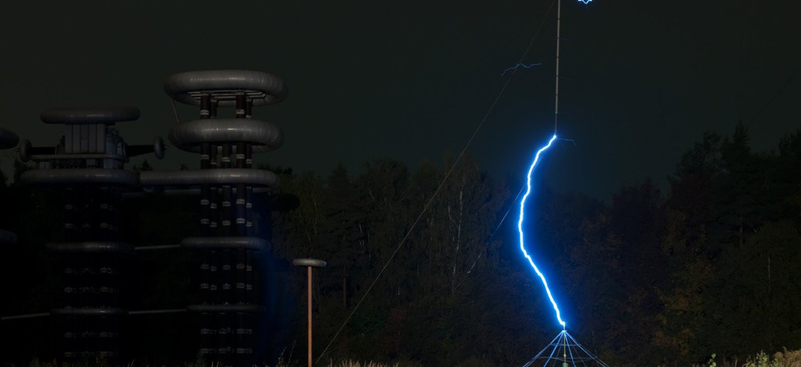
The above 9-megawatt Marx generator facility outside Moscow, built in the 1970s, is called the Istra High Voltage Research Center. The Russian version, sometimes called a "Tesla Tower," can emit energy equivalent to the electricity produced by combined power plants in Russia for 100 microseconds. Its original purpose was to serve as a testing ground during the USSR's quest to weaponize electromagnetic pulses. Today it is used to test for lightning protection. Marx generators of comparable scale are still in service in very large pulsed-power systems, including the Z Machine at Sandia National Laboratories, of which more shortly.
A note V1 did not have room for: the spark gap is not the only switch you can put in a Marx, and modern "solid-state Marx" generators replace the spark chain with stacks of MOSFETs or IGBTs gated by isolation transformers or fiber-optic links. The cascade physics is gone; each stage is now turned on by a deliberate command rather than by induced breakdown. That removes the spark gap's ferocious unpredictability but it also removes the cascade's natural rapidity, and getting a solid-state Marx to produce sub-nanosecond rise times is a real engineering problem. We will return to solid-state Marx generators in Chapter 6.
1.4 World War II and the Radar Revolution
Pulsed power as a discipline did not exist in 1939. Pulsed power as a discipline, recognizable, taught, funded, with its own journals and institutions, existed by 1945. The reason is radar.
A pulsed radar transmitter is a beautiful application of pulsed-power engineering. It needs to deliver a kilowatt or megawatt-class RF pulse, microseconds long, into an antenna, repeat it many hundreds or thousands of times per second, and recover quickly enough to receive the echo. The transmitter chain that does this is called a modulator, and it is the direct ancestor of every modern high-voltage pulse generator. Two basic modulator architectures emerged in the 1940s and remained dominant for decades:
The hard-tube modulator uses a vacuum tube, typically a triode or tetrode, as a series-pass element. Plate voltage is held off by the tube during the off state and the tube is driven into conduction during the pulse. The pulse shape is essentially controlled by the grid drive waveform. Hard-tube modulators are versatile, can produce arbitrary pulse shapes, and can be turned off mid-pulse. They were the workhorse of high-power radar from the 1940s through the 1980s and remain in service in some legacy systems. Their modern descendants are the half-bridge MOSFET pulsers, the BNC PVX-4110 and PVX-4150 are functionally hard-tube modulators with the tubes replaced by stacked MOSFETs and the grid drive replaced by a transformer-coupled gate driver.
The line-type modulator uses a pulse-forming network (PFN), a ladder of inductors and capacitors that emulates a charged transmission line, as the energy storage element, and a thyratron or hydrogen thyratron as the switch. When the thyratron fires, the PFN dumps its stored energy into a step-up pulse transformer, and the pulse shape is determined by the PFN's component values rather than by any active control. Line-type modulators are simpler, more rugged, and more efficient than hard-tube modulators, but they are also less flexible: the pulse shape is essentially baked into the network at design time. They dominated military and industrial radar for decades and are still found in linear accelerator drivers, klystron modulators, and certain high-power industrial applications.
The PFN is worth pausing on, because it is a piece of pulsed-power thinking that V1 did not cover and V2 must. The idea is to take a real charged transmission line, which would store and deliver a perfectly square pulse of duration equal to twice the line's electrical length, and approximate that line with lumped inductors and capacitors arranged in a ladder. With enough sections, the lumped-element approximation closely matches the distributed line, and you get a square pulse of arbitrary duration, limited only by the size of your inductors, without the impractical physical length of a real coaxial line. PFNs come in several canonical types (Guillemin Type A through Type E) that differ in how the L and C are arranged and what trade-offs they make between pulse flatness, parts count, and ease of charging. Chapter 6 develops PFNs in detail.

The hydrogen thyratron deserves mention because it was, for a generation of pulsed-power engineers, the switch. A gas-filled tube using hydrogen as the working gas, the thyratron could hold off tens of kilovolts, switch hundreds of amperes, recover in microseconds, and live for thousands of hours. It defined what a high-power pulser could do from roughly 1942 through roughly 1990. Its limitations, finite jitter, finite life, the need for a heater supply, the eventual decline of the gas, drove the search for replacements that culminated in the solid-state pulsers we use today. The thyratron is still manufactured, still sold, and still installed in new systems where its combination of voltage hold-off and current capacity is hard to match with semiconductors.
1.5 The Weapons-Physics Era and the Rise of the National-Laboratory Pulser
The other great driver of pulsed-power engineering in the twentieth century was nuclear weapons physics. The Manhattan Project and its successors needed devices that could deliver enormous current pulses to capacitor-bank-driven detonator arrays, to high-current spark-gap diagnostic flashlamps, to particle accelerators used for radiography of imploding components, and eventually to the high-energy laser and Z-pinch systems used for inertial-confinement fusion research. The U.S. national laboratories, Sandia, Los Alamos, Lawrence Livermore, became, almost incidentally, the world's largest pulsed-power research institutions.
Three technical lineages came out of that era:
The capacitor-bank revolution. Manhattan Project work created a demand for very large capacitor banks with very low parasitic inductance, capable of driving extremely fast current rises. The "rail-bus" capacitor bank, many small capacitors connected in parallel through low-inductance plate-and-strip transmission structures, became a standard architecture. Modern large pulsed-power machines descend directly from this work, and so do, at the other end of the size scale, the low-inductance ceramic capacitor arrays that BNC's high-current pulsers use to deliver hundreds of amps with sub-microsecond rise times.
Marx-Blumlein systems. A Blumlein line is a pair of charged transmission lines that, when switched, deliver a square pulse equal to the charging voltage (rather than half the charging voltage, as a single line would). Combine a Marx generator as the charger with a Blumlein as the pulse shaper and you have a machine that can deliver multi-megavolt, sub-microsecond pulses with reasonable efficiency. The Sandia Hermes series, the Aurora simulator at the Harry Diamond Laboratories, and the Sandia Saturn machine were all Marx-Blumlein systems. They were enormous, Saturn was a building, and they were the proving grounds for almost everything we now call pulsed-power engineering at the high end.
The Z Machine. Sandia's Particle Beam Fusion Accelerator (PBFA-II) was rebuilt in the 1990s and 2000s into the Z Machine, the world's most powerful laboratory radiation source. Z is a Marx-driven, water-line-pulse-shaped, magnetically insulated transmission line system that can deliver more than 25 megaamperes of current to a target in roughly 100 nanoseconds. It is used for radiation-effects testing, weapons-physics validation, and inertial-confinement fusion research. It is also a public reminder that pulsed-power scaling has no clean upper limit, Z is large, but it is not the largest possible machine, and proposed successors at higher energies have been studied seriously.
The relevant point for this book is that the engineering vocabulary of pulsed power, Marx, Blumlein, magnetically insulated transmission line, water dielectric, oil-insulated switch, fiber-optic trigger, was largely developed in service of physics programs that an instrument-scale user will never personally touch. But the techniques scaled down. A modern half-bridge pulser borrows trigger isolation from the national-laboratory tradition. A modern high-current laser-diode driver borrows low-inductance bus structures from the capacitor-bank tradition. A modern fast-rise generator borrows pulse-sharpening ideas from the work on Z and its predecessors. The lineage is unbroken even when the size scale differs by six orders of magnitude.
1.6 The Solid-State Revolution
For the first sixty years of pulsed power's history as a recognized discipline, the switch was a vacuum or gas device, a tube, a thyratron, a spark gap, an ignitron. By the early 1990s, all of these were under serious challenge from solid-state semiconductors, and by 2010 the challenge was largely complete: most new commercial pulse generators in the kilovolt-and-below range used silicon power semiconductors as their primary switches, and the gas-and-vacuum incumbents had retreated to the very-high-voltage and very-high-current niches where their physics still had the edge.
The solid-state revolution had three waves.
Wave one: power MOSFETs (1970s through early 1990s). The vertical-channel power MOSFET, commercialized in the late 1970s, gave pulsed-power engineers a switch that combined the voltage hold-off of a tube with the gate-drive simplicity of a small transistor. Early devices were limited to a few hundred volts and a few amperes, and getting to higher voltages required series-stacking techniques borrowed from the high-voltage power-electronics tradition. The breakthrough was that MOSFETs could be paralleled cleanly (their on-resistance has a positive temperature coefficient, so paralleled devices share current automatically) and they could be stacked in series with appropriate gate-drive isolation. By the late 1980s, pulse generators using stacks of power MOSFETs in half-bridge or push-pull topologies could match thyratron performance up to roughly 10 kV and were beginning to displace gas-tube modulators in the commercial radar and laser markets.
Wave two: IGBTs (1990s through 2010s). The insulated-gate bipolar transistor combined the voltage hold-off and current density of a bipolar transistor with the gate-drive simplicity of a MOSFET. IGBTs could be built in single dies that hold off several kilovolts and switch hundreds of amps, which made them extremely attractive for medium-voltage pulser applications where the parts count of a MOSFET stack would have been impractical. The trade-off is switching speed: IGBTs are slower than MOSFETs and they have a "tail current" at turn-off that limits their use in fast-rise applications. They came to dominate pulse-generator design in the kilovolt-and-below range where switching speed is not the binding constraint, including motor drives, induction heating, and a wide range of industrial pulsed processes.
Wave three: wide-bandgap devices (2010 onward). Silicon carbide (SiC) MOSFETs and gallium nitride (GaN) high-electron-mobility transistors (HEMTs) crossed the commercial threshold in the early 2010s, with SiC MOSFETs first reaching 1200 V production volumes around 2011 and discrete GaN HEMTs becoming widely available shortly after. Wide-bandgap devices have higher breakdown fields than silicon (roughly ten times higher for SiC, somewhat higher again for GaN), which means they can hold off the same voltage in a thinner die and switch faster as a result. The practical consequence for pulsed power is that SiC and GaN devices can deliver rise times in the sub-nanosecond range at voltages where silicon is still recovering from turn-on, and they can dissipate the heat to do it repetitively at frequencies silicon cannot reach. Chapter 5 covers wide-bandgap devices in detail, because they are the largest single change in the pulse-generator landscape since V1 was published.

There is a fourth category worth flagging here, though it remains a research and specialty market: ultra-fast diode and switch technologies that are not transistors at all. Drift-step-recovery diodes (DSRDs), silicon opening switches (SOS), and photoconductive semiconductor switches (PCSS) each exploit specific semiconductor physics to deliver pulse-sharpening or pulse-generation capabilities that conventional switches cannot match. A DSRD can produce sub-nanosecond rise times at tens of kilovolts in a way no MOSFET can. A PCSS triggered by a femtosecond laser can produce picosecond rise times at field strengths approaching the bulk breakdown of the semiconductor. These devices are not yet ubiquitous, but they have moved from the laboratory into commercial pulse generators in specialty markets including ultra-wideband radar, electromagnetic-effects testing, and precision physics experiments. Chapter 5 introduces them.
1.7 The Instrument Industry: From Custom Rigs to Commercial Pulsers
For most of pulsed power's history, a researcher who needed a high-voltage or high-current pulser built one. The components were available, capacitors, gas tubes, transformers, transmission line, but the system integration was specialty work, and a modulator in 1970 was as much a one-off engineering project as a particle accelerator. Two trends changed this through the 1980s and 1990s. First, the solid-state revolution lowered the integration burden: a MOSFET stack with a transformer-coupled driver is much easier to package as a benchtop instrument than a thyratron with its heater supply, reservoir control, and high-vacuum considerations. Second, the application set broadened: pulsed-laser-diode drivers for industrial range finding and medical lasers, electrostatic accelerator extractors for time-of-flight mass spectrometry, and Pockels-cell drivers for laser Q-switching all created sustained commercial demand for instrument-grade pulse generators that could be specified, ordered, and supported without a custom-engineering engagement.
The companies that grew up to serve this demand defined the modern instrument-grade pulser market. Directed Energy, Inc. (DEI) was founded in 1987 in Fort Collins, Colorado, originally to commercialize a patented low-inductance MOSFET package and high-frequency switching products. Over the 1990s and 2000s, DEI broadened into instrument products, turnkey pulse generators for laser-diode drivers, high-voltage modulators, and Pockels-cell drivers, that gave researchers an alternative to building their own. Berkeley Nucleonics Corporation (BNC), founded in 1963 in San Rafael, California, originally built precision pulse and delay generators for nuclear-research timing applications and grew into a broad signal-generator manufacturer. The two companies' product lines were complementary, DEI's high-power pulsers paired naturally with BNC's precision timing generators, and after years of cooperation, BNC acquired the DEI product line in 2021. The BNC-DEI line described in Chapter 9 is the result of that consolidation: a unified portfolio that spans precision timing, low-voltage signal generation, kilovolt-class high-voltage pulsers, and hundred-amp-class current pulsers, all engineered to interoperate and supported through a common service organization.
A handful of other firms, FID Technology, Eagle Harbor Technologies, Megaimpulse, Stangenes Industries, Pulserlab, and others, occupy adjacent niches in the modern pulsed-power instrument market. Each has its own technology focus: FID is associated with semiconductor opening-switch and DSRD-based ultra-fast pulsers; Eagle Harbor with high-voltage nanosecond pulsers and inductive adders; Megaimpulse with high-current research pulsers; Stangenes with pulse transformers and component-level building blocks. The market is small enough that practitioners know one another's product lines well, and an instrument selection in a contemporary lab usually involves choosing between two or three vendors who cover overlapping but distinguishable specifications. Chapter 9 places the BNC-DEI line in that broader context.
1.8 The State of the Art as of V2
Three observations summarize where pulsed power stands as of this writing.
Voltage and rise-time records continue to fall, mostly through smarter switching. The commercial state of the art for benchtop pulsers includes sub-nanosecond rise times at kilovolt amplitudes, multi-kilohertz repetition rates at tens of kilovolts, and hundred-ampere-class current pulsers with sub-microsecond pulse widths and stripline-grade pulse fidelity. None of these are research curiosities, they are products on a price list. Five years ago, several of them were not.
The application set is broadening faster than the technology is. Pulsed electric field bioelectrics, irreversible electroporation for tumor ablation, food and water sterilization, FMCW LiDAR, fusion-driver R&D, additive manufacturing, plasma medicine, and pulsed-microwave systems for both communications and effects testing are all driving demand for pulsers with specifications that did not have a market five or ten years ago. A pulser optimized for electroporation looks quite different from a pulser optimized for time-of-flight mass spectrometry, and the diversity of "what a pulse should look like" is producing a corresponding diversity of products. Chapter 10 surveys this application landscape.
Wide-bandgap is the inflection point. Almost every interesting product development of the last five years either uses SiC or GaN devices directly, or is responding to the new specifications that SiC and GaN devices have made possible. SiC has redefined the kilovolt class of switches; GaN has redefined the sub-nanosecond rise-time class. Together they have moved performance benchmarks that were stable for two decades. The implications work their way through the rest of this book.
The chapters that follow take that state of the art apart, piece by piece, and put it back together as a working understanding. We start in Chapter 2 with the fundamentals, what voltage and current pulsers actually are, how they categorize, what the key specifications mean, and work outward from there toward switches, topologies, diagnostics, applications, and the future. By the end, you should be able to read any commercial pulser data sheet and know what it is telling you, identify the right pulser for an application you are working on, and have a clear-eyed view of what the next generation of devices will and will not be able to do.
A century after Erwin Marx, the field is more interesting than it has ever been.
1.9 Questions for Review
-
What three nineteenth-century technologies are the building blocks of every modern high-power pulse generator? a. Resistor, transistor, integrated circuit b. Capacitor, transformer, switch c. Battery, motor, generator d. Antenna, oscillator, receiver
-
The Marx generator was first demonstrated by Erwin Marx in approximately what year? a. 1888 b. 1924 c. 1945 d. 1970
-
Which of the following best describes a pulse-forming network (PFN)? a. A computer algorithm that designs pulse waveforms b. A ladder of lumped inductors and capacitors that emulates a charged transmission line c. A type of capacitor specialized for pulsed discharge d. A feedback loop that regulates the flat-top of a pulse
-
For roughly fifty years, which switch was the dominant high-power choice in line-type radar modulators? a. The power MOSFET b. The silicon carbide MOSFET c. The hydrogen thyratron d. The gallium nitride HEMT
-
Which device family launched the first wave of the solid-state revolution in pulse generators? a. Insulated-gate bipolar transistors (IGBTs) b. Vertical-channel power MOSFETs c. Photoconductive semiconductor switches (PCSS) d. Drift-step-recovery diodes (DSRDs)
-
Which wide-bandgap development is described as the inflection point for the kilovolt class of switches? a. The return of the spark gap b. The decline of the hydrogen thyratron c. Silicon carbide (SiC) MOSFETs reaching production volumes d. The first vacuum triode modulator
-
How did Berkeley Nucleonics Corporation come to offer the DEI high-power pulser line? a. BNC developed the line independently in the 1980s b. BNC acquired the Directed Energy, Inc. product line in 2021 c. BNC licensed the line from a national laboratory d. The two companies have always been a single firm
Test yourself
The same seven questions, graded instantly with your score saved on this device.